
120Vac Vent Switch, Adaptor 1101-05A and Replacement Air Damper, Power Close:
#6B5. Ventilation Switch and Fan, Relay Adaptor (ADP-1101-05A), One Power Close Fresh Air Damper (-PC) Opens during Venting.
HMI Hoyme Manufacturing Inc. Special Note: Circuits are colored for clarification only and are not necessarily those found in actual installations. Combustion Air Damper Wires, however, are colored as shown.
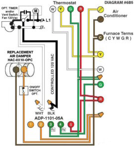
Diagram #6B5: Forced Air Furnace having a replacement air supply duct together with an exhaust fan controlled by a designated ventilation switch and/or bathroom timer.
1. Replacement Air Control Damper (HAC-0x10-OPC) – (Power Close)
2. Ventilation Switch and/or bathroom timer to supply Controlled 120Vac to furnace area.
3. Relay Adaptor (ADP-1101-05A) to function as a control centre.
OPERATION:
1. Replacement Damper opens to provide fresh air during the ventilation cycle.
2. Ventilation Switch and/or bathroom timer turns on Ventilation Fan, opens Replacement Air Damper and turns on Furnace Fan simultaneously.
3. Damper will remain closed during manual furnace fan operation.
4. On/Off Switch connected to the Adaptors (as shown) allows manual control of the Replacement Air Damper to open as required.