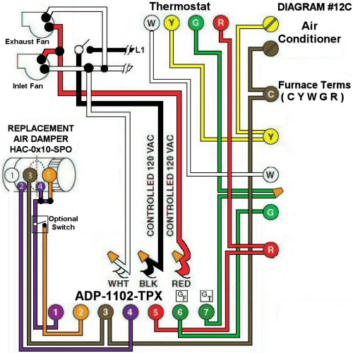
High volume Kitchen Exhaust fan interconnected to a Forced Air Heating System, replacement air with inlet fan interlocked with a Power Open Damper:
#12C. High volume Kitchen Exhaust Fan and an Inlet Supply Fan interconnected to a Forced Air Heating System with an interlocking Inlet Power Open Replacement Air Damper (HAC-0x10-SPO) c/w End Switch and an Adaptor (ADP-1102-TPX) but Replacement Air Damper does not Open during Furnace firing.
HMI Hoyme Manufacturing Inc. Special Note: Circuits are colored for clarification only and are not necessarily those found in actual installations. Combustion Air Damper Wires, however, are colored as shown.
Diagram #12C: A High Volume Kitchen Exhaust Fan interlocked to both a Power Open Damper and an Inlet Booster Fan to form part of a Forced Air Heating System.
NOTE: If combining this High Volume Exhaust System with an existing designated Ventilation System, go to Coloring Diagram (#12D) or (#12D1) for instructions.
- Power Open Damper with an End Switch (HAC-0x10-SPO) where “x”= diameter
- Ventilation Switch and or Bathroom Timer with 3C-Wire 120Vac supply to Furnace area
- Relay Adaptor (ADP-1102-TPX) to function as a control center
OPERATION:
- Thermostat does not control the Damper. (If required go to Diagram #12D1)
- The Kitchen Ventilation Switch signals the Adaptor to start the Furnace Circulation Fan and to open the Replacement Air Damper
- Optional on/off Switch connected between #1 and #2 of the (ADP-1102-TPX) allows full control of the Replacement Air Damper to open as required
- After the Inlet Damper proves to be open, the Damper End Switch turns on both the Inlet Booster Fan and the High Volume Exhaust Fan. The Fans are, therefore, Inter-locked to run only after the Damper proves to be open to supply the replacement air
Option: Consider an Inline Electric Heater with an Airflow Switch to temper cold incoming air.

