
120 Vac Vent Switch, Adaptor 1102-TWP and Replacement Air Damper, Power Open with high volume Kitchen Exhaust Fan interconnected to a Forced Air Heating System, replacement air with Inlet Fan interlocked with a separate Power Open Damper:
#12D1. Same as #12C but uses Adaptor (ADP-1102-TWP) to Open The Furnace Replacement Air Damper during Furnace firing.
HMI Hoyme Manufacturing Inc. Special Note: Circuits are colored for clarification only and are not necessarily those found in actual installations. Combustion Air Damper Wires, however, are colored as shown.
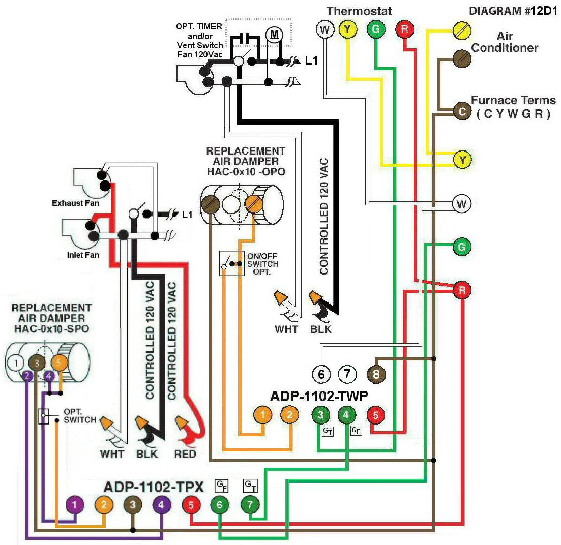
Diagram #12D1: Forced Air Furnace having a Regular Replacement Air Supply Duct with an Inlet Damper and an Exhaust Fan controlled by a designated Ventilation Switch. In addition, a special Replacement Air supply Duct with a Power Open Damper with End Switch, a Booster Inlet Fan and a High Volume Exhaust Fan.
- Replacement Air Control Damper (HAC-0x10-OPO) where “x”= diameter
- Ventilation Switch to supply Controlled 120Vac to Furnace area
- Relay Adaptor (ADP-1102-TWP) to function as a control center for regular ventilation
- Power Open Damper with an End Switch (HAC-0x10-SPO) INTERLOCKED to an Inlet Fan to supply extra replacement air for a high volume Exhaust Fan
- Interface Relay Adaptor (ADP-1102-TPX) acts as a control center for the extra replacement air
OPERATION:
- Replacement Air Damper opens during Furnace firing
- The designated Ventilation Switch simultaneously turns on the Exhaust Fan, the Furnace Fan and opens the Replacement Air Damper
- Optional on/off Switch connected between #1 and #2 of the Adaptor (ADP-1102-TWP) or (ADP-1102-TPX) allows full control of the Replacement Air Dampers to open as required
- In addition, the high volume Exhaust Fan switch signals the Adaptor (ADP-1102-TPX) to start the Furnace Circulation Fan and open the extra Replacement Air Damper
- After the extra Damper with End Switch proves to be open, both the Inlet Booster Fan and the high volume Exhaust Fan turn on. The Fans are, therefore, Interlocked to run only after the Inlet Damper is open for replacement air
Option: Consider an Inline Electric Heater with an Airflow Switch to temper incoming cold air.