
Combustion Air Damper with Heat Limit Switch:
#1A. Combustion Air Damper (HOM-0x11-SF1) Interlocked to a Furnace and Interconnected to a DHW with a Heat Limit Switch.
HMI Hoyme Manufacturing Inc. Special Note: Circuits are colored for clarification only and are not necessarily those found in actual installations. Combustion Air Damper Wires, however, are colored as shown.
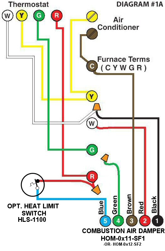
Diagram #1A: A Forced Air Furnace or Boiler having a Combustion Air Supply Duct.
- Combustion Air Damper (HOM-0x11-SF1) for one Furnace or Boiler
- Optional Heat Limit Switch (HLS-1100) that opens on temperature rise
OPERATION:
Combustion Air Damper is interlocked to the Thermostat/Aqua-Stat and the Gas Valve so that the Damper proves to be open to supply fresh air before the Furnace/Boiler fires. The Damper closes to conserve energy when the fire stops. An Optional Heat Limit Switch may be added in series with the 24Vac Power Supply to the live side of the motor to cause the Damper to open simultaneously with the sensing of a temperature rise of 130ºF.