
Installation instructions – Printer friendly (pdf)
ADP-0243-S5A – Information Page
Installation Instructions for HMI HOYME Adaptor 0243- S5A
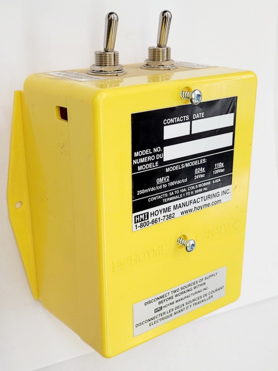
- 4” x 5” x 2 1/2” (101 x 127 x 64 mm)
- Interlocks 24Vac Combustion Air Control Damper
- (Type SF1) to Two Separate Safety Control Circuits
- This 24Vac Adaptor, with three Relays, is designed to be interlocked to two separate 24Vac safety control appliance stats controlling one 24Vac damper (HOM-0x11-SF1)
- Installation of this Adaptor shall be in accordance with the requirements of the authorities having jurisdiction
Refer also to HMI HOYME Installation Instructions for ‘Combustion Air Control Damper, Series ‘HOM‘
This 24Vac Adaptor proves to be open before one or both appliances fire separately or together. A third heating appliance stat can be added by using a Combustion Air Control Damper (HOM-0x12-SF2) that has two separate interlocking circuits combined with this adaptor (Check size of Combustion Air Duct to meet local Codes)
Adaptors are also available for 120Vac or a 0.25 to 100 Vdc safety control circuits (one for each appliance up to three) interlocked to one HOM-0x11-SF1 (Check size and capacity of combustion air duct)
I.D.: ADP – 0243 – S5A Includes:
- 1 ea – DPDT Relay, Coil-24Vac Contacts-5 Amps
- 2 ea – SPDT Relay, Coil-24Vac Contacts-5 Amps
- 2 ea – TEST/RUN on/off manual Switches
Requirements:
- Adaptors may be mounted on a wall or on the side of appliance control box
- Leads must be suitably cabled and fastened
- Refer to local Electrical Codes
- If required, use an approved 24Vac Transformer of adequate capacity (10 VA)
- Supply for the transformer primary shall be taken from the line voltage supply for the appliance. Refer to applicable codes
- Always conduct a thorough checkout after installation is complete
- Affix attached wiring diagram label adjacent to heating appliance wiring diagram label
Note: Where a low limit may allow operation of the Burner or Fuel Valve when stat is not calling for heat, damper shall be used only in conjunction with Adaptor as shown
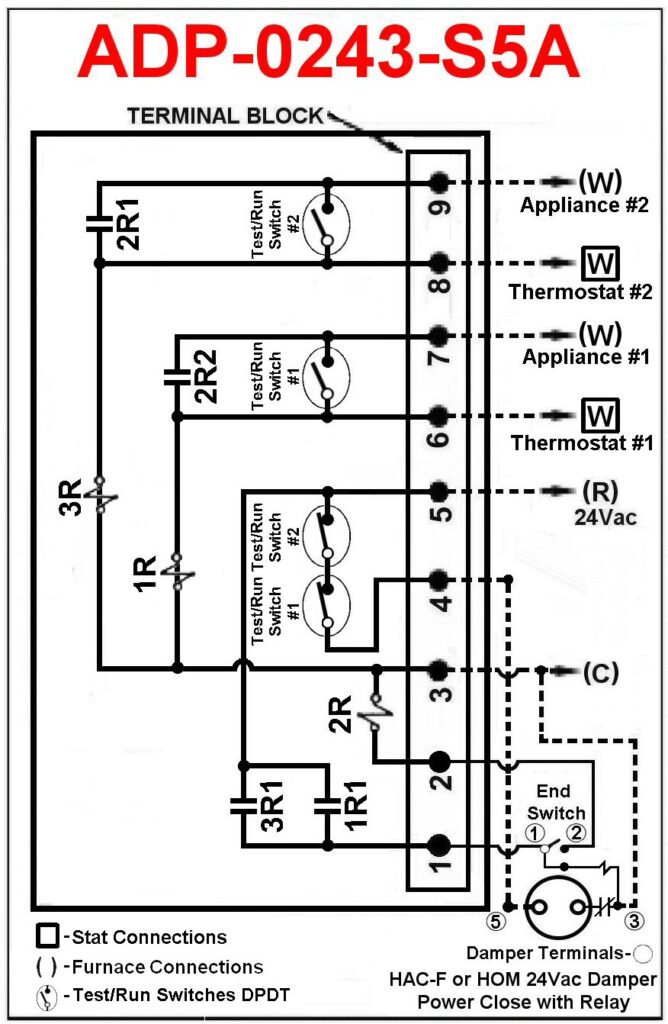
A. Connect ADP-0243-S5A to number one appliance and to Damper HOM-0x11-SF1
- Turn stat controls to lowest setting.
- Turn off power to heating appliances.
- Connect Adaptor Terminal 5 to (R) on number one appliance terminal strip
- Connect Adaptor Terminal 3 to (C) on number one appliance terminal strip
- Connect damper wires BLACK (1), RED (2), BROWN (3) and BLUE (5) to Adaptor terminals 1, 2, 3 and 4 respectively. (Note: damper #5 connects to adaptor #4) See wiring diagram
- Test by turning on power supply. Damper will close
Note: ‘TEST/RUN’ manual switches on the damper and adaptor are to be in the ‘RUN’ position
B. Connect number one appliance stat to Adaptor ADP-0243-S5A
- Turn off power supply on number one appliance and set thermostat to lowest setting
- Remove stat wire from terminal strip (W) and connect to Adaptor #6. Add a length of wire as required to connect Adaptor #7 to appliance (W)
- Turn power on to number one appliance and damper will close
- Turn stat to call for heat and damper will open and cause appliance number one to fire.
- Turn stat down. Fire stops and damper closes
C. Connect number two appliance stat to Adaptor ADP-0243-S5A
- Turn off power on second appliance and set stat to lowest setting
- Remove stat wire from terminal strip (W) and connect to Adaptor #8. Add a length of wire as required to connect Adaptor #9 to appliance (W)
- Turn power on to number two appliance and damper will close
- Turn stat to call for heat and damper will open to cause number two appliance to fire
- Turn stat down. Fire stops and damper closes
NOTE: Check size and capacity of combustion air duct before allowing two or more appliances to share one combustion air duct
D. A third appliance may be added by replacing the HOM-0x11-SF1 with the HOM-0x12-SF2 and follow installation instructions supplied with the Damper (Follow local Codes for combustion air supply)
DO NOT USE GREEN WIRE FOR GROUND. Green Wire is to be used only when connecting to an ‘HAC’ type 24Vac Fresh Air Damper
Schematic Wiring Diagram – ADP-0243-S5A
Combustion Air Control Damper HOM-0x11-SF1 Interlocked to one or two Heating Appliances using Adaptors
Note: This marking is also on label to be affixed adjacent to the appliance wiring diagram. When completing electric circuits, additional wire shall be of the same size as originally used
For more information, please contact HMI HOYME Manufacturing Inc. @ 1-800-661-7382
Installation instructions – Printer friendly (pdf)
ADP-0243-S5A – Information Page