
120Vac Vent Switch, Adaptor 1101 and Replacement Air Damper, Power Close, opens during firing:
#6A2. Three 120vac Double Pole Ventilation Fan Switches and Exhaust Fans, Adaptor (ADP-1101-05A) and Power Close Replacement Air Damper c/w Relay (-PC), Opens during Furnace Firing.
HMI Hoyme Manufacturing Inc. Special Note: Circuits are colored for clarification only and are not necessarily those found in actual installations. Combustion Air Damper Wires, however, are colored as shown.
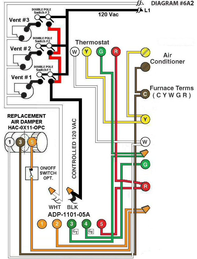
Diagram #6A2: Forced Air Furnace having a Replacement Air Supply Duct together with two (or more) Exhaust Fans controlled by two (or more) separate Double Pole Ventilation Switches.*
- Replacement Air Control Damper (PC) with Relay (HAC-0x11-OPC)
- Two (or more)Ventilation Switches to supply Controlled 120Vac to Furnace area
- Relay Adaptor (ADP-1101-05A) to function as a control center
OPERATION:
- Replacement Damper opens to provide fresh air during the Ventilation and Heating Cycle
- Each Double Pole Ventilation Switch turns on its own Ventilation Fan, opens Replacement Air Damper and turns on Furnace Fan simultaneously
- Optional Switch (i.e. toggle switch) allows full control of the Replacement Air Damper to open as required provided it is PC type
N.B. Replacement Air Damper is not affected by the ‘Manual’ setting of the Furnace Fan.
*Alternately, when using two (or more) regular Ventilation Switches (or timers), instead of the DP type shown here, to control two (or more) Exhaust Fans and involving only one Furnace, use one Relay Adaptor for each Timer/Exhaust Fan(see Diagram #6). Connect relay Adaptor terminals 1-1, 2-2, 5-5 and connect terminal 3(GT) of the first Adaptor to G of the Thermostat and 4(GF) – 3(GT) of the next Adaptor. The last Adaptor connect 4(GF) to G on the Furnace as shown.