
Two Forced Air Furnaces sharing a Replacement Air Supply Duct controlled by one Fresh Air Damper with Power Open Damper:
#8B1. Forced Air Furnace with Power Close Replacement Air Damper (HAC-0x11-OPC) c/w Relay and a Ventilation Switch that uses Adaptor (ADP-0241-10A) to ventilate and also Open during Furnace firing.
HMI Hoyme Manufacturing Inc. Special Note: Circuits are colored for clarification only and are not necessarily those found in actual installations. Combustion Air Damper Wires, however, are colored as shown.
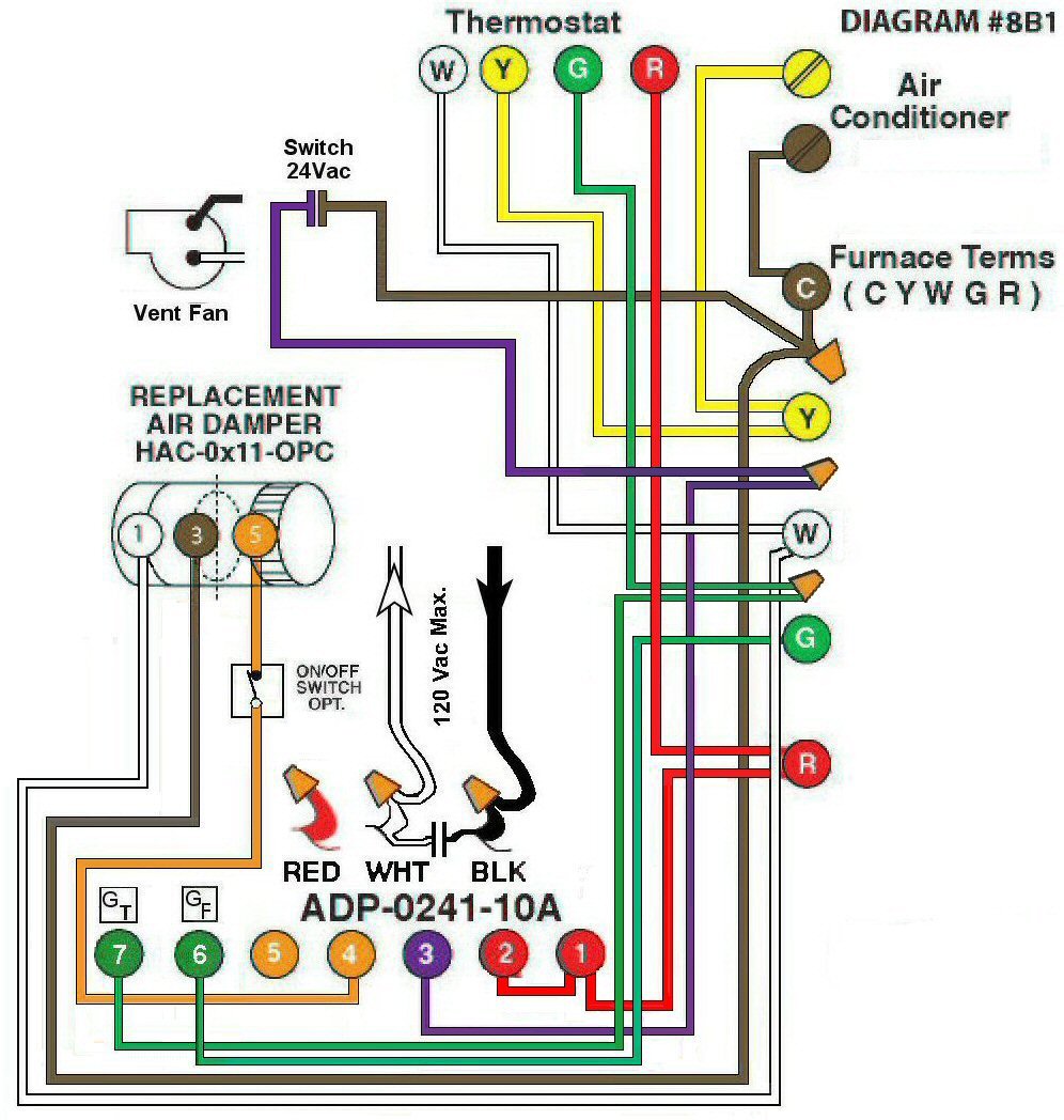
Diagram #8B1: Forced Air Furnace having a Replacement Air Supply dDuct together with an Exhaust Fan controlled by a designated 24Vac Ventilation Switch.
- Replacement Air Control Damper, Power Close (HAC-0x11-OPC)
- 24Vac Ventilation Switch
- 24Vac Relay Adaptor (ADP-0241-10A) to function as a control center connected to the Exhaust Fan
OPERATION:
- Furnace fires with Thermostat signal and opens the Replacement Air Damper
- 24Vac Ventilation Switch turns on Ventilation Fan, opens Replacement Air Damper and turns on Furnace Fan simultaneously
- Optional Switch (i.e. toggle switch, de-humidistat) allows full control of Replacement Air Damper to open as required
N.B. Replacement Air Damper is not affected by the ‘Manual’ setting of the Furnace Fan.