
ADP-0MV2-S5A Installation instructions – Printer friendly (pdf)
ADP-0MV2-S5A – Information Page
Installation Instructions for HMI Hoyme ADP-0MV2-S5A
ADP-0MV2-S5A Interlocks 24Vac Combustion Air Control Damper To 250mVdc/100 Vdc Safety Control Circuits
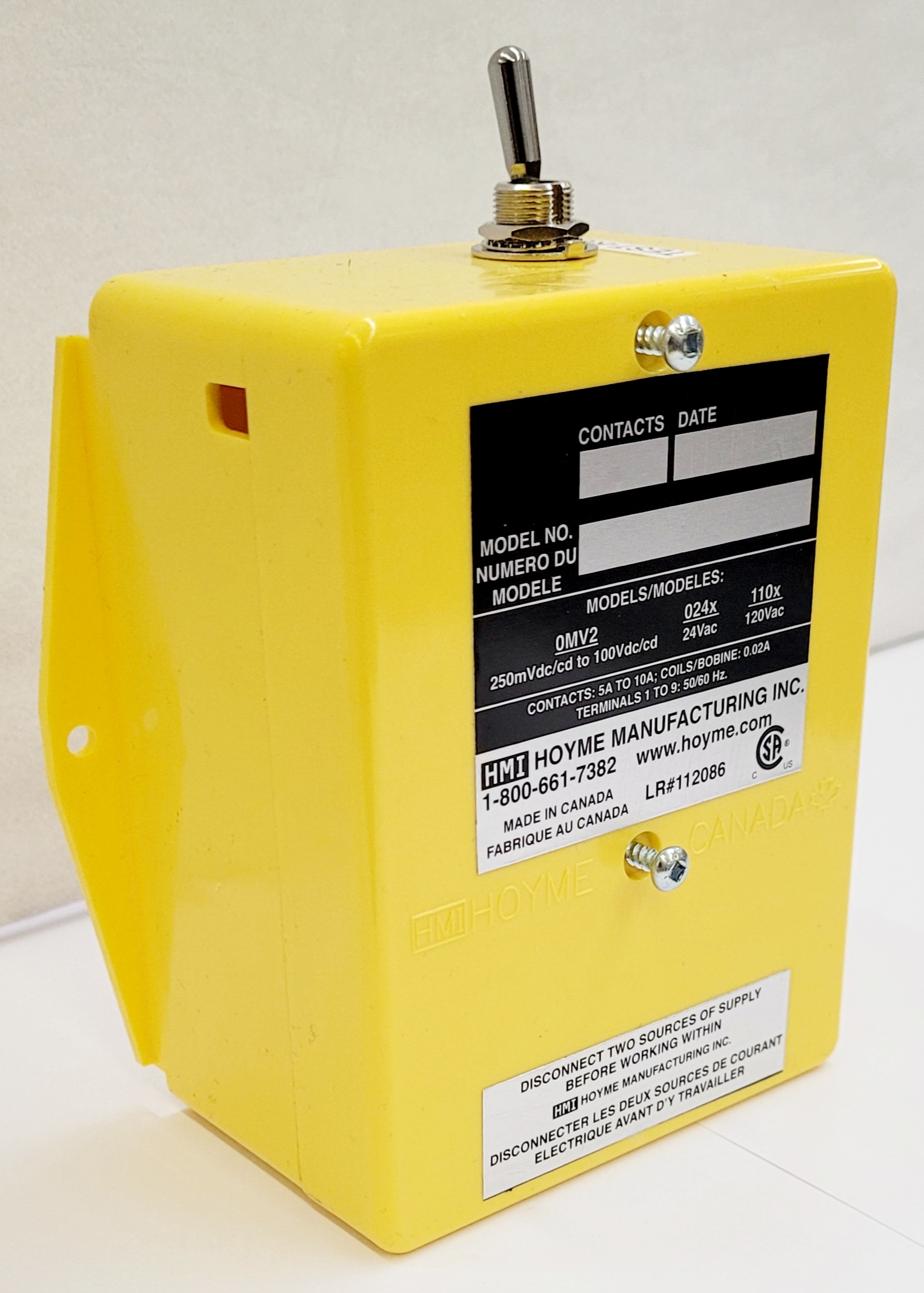
- 4” x 5” x 2 1/2” (101 x 127 x 64 mm)
- This Adaptor comes with two relays and a printed circuit which senses a 250 mVdc/100 Vdc safety control circuit, opens a 24Vac damper and then signals back to the safety circuit for firing.
- For line voltage AC safety control circuits, use Adaptor ADP-1102-S5A

Installation of this Adaptor shall be in accordance with the requirements of the authorities having jurisdiction
Refer to HMI HOYME Installation Instructions: ‘Combustion Air Control Damper, Series HOM’
ADP-0MV2-S5A Includes:
- Test/Run Switch
- Printed Circuit Board with Relays
- Main Coil 24Vac. Points 24Vac/5Amps
- For one appliance, use one Adaptor and one Damper, Series HOM, Type – SF1
- For two appliances, use two Adaptors and one Damper, Series HOM, Type – SF1
- Adaptor is to be mounted as close as possible to 250 mVdc/100Vdc gas valve
- Additional wire shall not be spliced to the RED, BLACK or WHITE leads
- Use an approved 24Vac transformer of adequate capacity (10 VA min.)
- Supply for the primary of the transformer shall be taken from the line voltage supply for the appliance. Refer to applicable codes
- Affix attached wiring diagram label adjacent to appliance wiring diagram label
Below includes inter-connecting the Adaptor to the Damper
‘TEST/RUN’ manual switches on the damper and adaptor are to be in the ‘RUN’ position.
- Turn temperature control to lowest setting
- Turn off electric power. Add a 24Vac transformer to power the Damper Closed
- Follow applicable Codes
- Connect damper wires BLACK (1), RED (2), BROWN (3) to Adaptor terminals 1, 2 and 3 respectively
- Connect damper wire BLUE (5) to Adaptor terminals
- Connect 24Vac transformer wires to Adaptor terminals 3 and 5
- Turn on electric power to transformer. Damper will close
- Test for common ground by touching WHITE Adaptor lead to base of gas valve. If sparking occurs, interchange transformer wires on Adaptor terminals 3 and 5
Below includes inter-connecting the Adaptor to the Power Pile of a mVdc Circuit
- Pilot light to remain burning
- Adaptor leads BLACK and WHITE must be properly matched to the dc polarity of the power pile with the Pilot light burning
- Test by touching Adaptor WHITE lead to Thermopile Wire on terminal (PP) on Coil side of the gas valve while touching Adaptor BLACK lead to remaining thermopile wire. Damper should now open. If no response, exchange Adaptor leads and retest
- Take Note of this WHITE ‘Lead/Thermopile’ wire combination
- Connect this WHITE ‘Lead/Thermopile’ wire combination to (PP) terminal on Coil side of the gas valve. (This might require inter-changing thermopile wires and relight pilot if necessary.)
- Disconnect temperature control wire leading to the TH terminal on Gas Valve Coil and replace with the Adaptor RED wire
- Rejoin the temperature control wire to the Adaptor BLACK lead with a screw-on wire connector
- Turn temperature control to call for heat – Damper will open and heating appliance will operate normally
- Always conduct a thorough check-out after installation is complete
Below includes inter-connecting the Adaptor to dc Circuits other than the mVdc
Safety Note: Higher voltage requires EXTRA CAUTION
- Adaptor leads BLACK and WHITE must be properly matched to the dc polarity of the safety circuit
- Test by touching Adaptor WHITE and BLACK wires to the dc source leading to the gas valve. If damper does not open, reverse the Black and WHITE leads and the damper will open. Note this polarity combination
- With voltages other than mVdc, turn the supply power off
- Connect the WHITE lead wire to the gas valve as per polarity combination found above under Inter-Connecting the Adaptor to the Power Pile of a mVdc Circuit
- On the other side of the gas valve disconnect the dc wire and replace it with the Adaptor RED wire
- To the wire removed above located under: (Inter-Connecting the Adaptor to the Power Pile of a mVdc Circuit – Disconnect temperature control wire leading to the TH terminal on gas valve coil and replace with the Adaptor RED wire), connect the Adaptor BLACK wire with the wire nut supplied
- Turn on the power, turn temperature control to call for heat, damper will open and heating appliance will operate normally
- On DC CIRCUITS other than mVdc circuits, the BLACK and WHITE leads of shall also be matched to the dc polarity of the safety circuit.
- Adaptor leads BLACK, RED and WHITE are to be connected to the 250mVdc/100Vdc safety circuit only.
Schematic Wiring Diagram for Combustion Air Control Damper
Interconnected to Millivolt Safety Control Circuit Adaptor “0MV2”
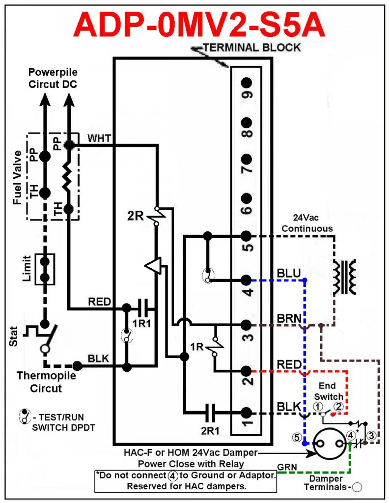
Note: This marking is also on label to be affixed adjacent to appliance wiring diagram.
Additional wire shall be of the same size and type as originally used when completing the above circuit.
For more information, please contact HMI HOYME Manufacturing Inc. @ 1-800-661-7382
Installation instructions – Printer friendly (pdf)
ADP-0MV2-S5A – Information Page