
Installation instructions – Printer friendly (pdf)
ADP-1102-10A – Information Page
Installation Instructions for HMI HOYME ADP-1102-10A
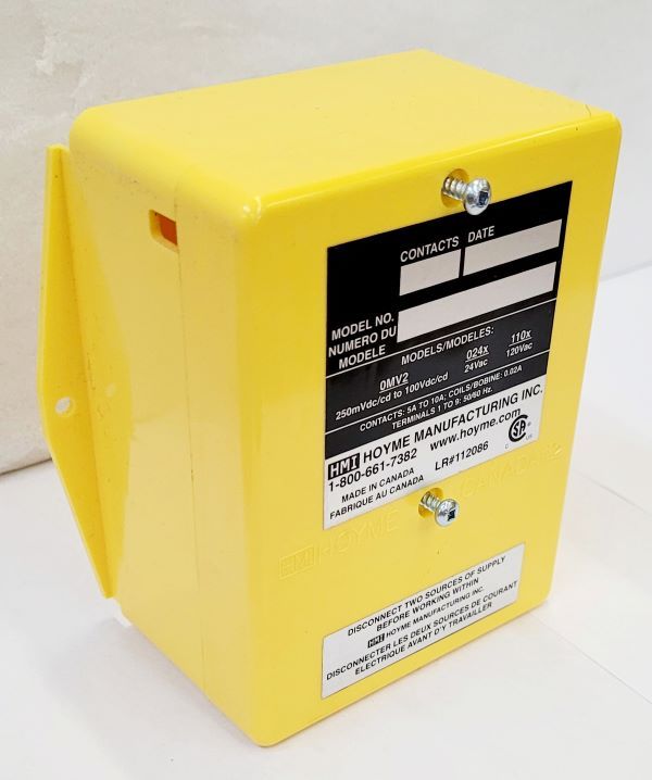
- 4” x 5” x 2 1/2” 101 x 127 x 64 mm)
- Handles Fan Loads up to 10A & Interlocks 24Vac Combustion Air/Flue Damper to 120Vac Safety Control Circuit
- This 120Vac Adaptor, handles loads up to 10Amps, senses a line voltage safety control signal, proves a 24Vac damper to be open (Interlocked) and then sends the signal back to the line voltage control circuit. For Safety Control Systems using 250mVdc to 100Vdc, use ADP- 0MV2-S5A and follow its Installation instructions.

Installation of this Adaptor shall be in accordance with requirements of the authorities having jurisdiction
Refer also to HMI HOYME Installation Instructions: ‘Combustion Air Control, Series HOM’ for Combustion Air; Series HAC-‘F’ Flue Damper
I.D.: ADP- 1102 – 10A; Comes with 2 Relays
- 1-120Vac Coil, Contacts 5 Amps, DPDT
- 1- 24Vac Coil, Contacts 10 Amps, SPDT
Fitness of this Adaptor/Damper combination to satisfy air supply requirements for fuel fired appliances during operation of the interconnected Exhaust Fan(s) shall be investigated by the enforcing authorities
Requirements
- For one appliance, use one Adaptor and one Damper, Series HOM-SF1/HAC-F
- For two appliances, use two Adaptors but only one damper, Series HOM-SF1/HAC-F
- Adaptors may be mounted on side of appliance control box.
- Leads must be suitably cabled and fastened
- if Adaptor is mounted away from control box, line voltage leads shall be enclosed in suitable raceways. Refer to local electric codes
- Use an approved 24Vac Transformer of adequate capacity (10 VA min)
- Supply for the transformer primary shall be taken from the line voltage supply for the appliance. Refer to applicable codes
- Always conduct a thorough checkout after installation is complete
- Affix attached wiring diagram label adjacent to appliance wiring diagram label
Note: For controlled circuits having a capacity equal to the load, use wiring diagram, Option #1.(10 Amps Max) See Wire Diagram
For control circuits having a capacity less than the load, use Option number #2
- Turn temperature control to lowest setting
- Turn off electrical power to heating appliance
- Disconnect controlled line voltage lead from the load terminal
- For Option #1 use a screw-on wire connector to join Adaptor Black & Blue lead to the controlled line voltage as in 3 above. For Option #2 join Adaptor Black lead only to the controlled line voltage and a Blue lead directly to120Vac line
- Join the remaining Adaptor Blue lead to the load
- Connect Adaptor WHITE lead to the common side of the line voltage
- Connect damper wires BLACK (1), RED (2), BROWN (3) and BLUE (5) to Adaptor Terminals 1, 2, 3 and 5 respectively
- Connect 24Vac continuous supply to Adaptor Terminals 3 and 5
- Turn on electrical power supply. Damper will close. Note: ‘TEST/RUN’ manual switch shall be in the ‘RUN’ position
- Turn temperature control to call for heat. Damper will Open and the appliance will operate normally
Note: Where a low limit may allow operation of the burner or fuel valve when thermostat is not calling for heat, Damper shall be used only in conjunction with Adaptor as shown
Additional wire shall be of the same size as originally used when completing electric circuits
Schematic Wiring Diagram for Combustion Air/Flue Control Damper Interlocked to Line Voltage – Safety Control Circuit Using Adaptor ADP-1102-10A
Note: This marking is also on label to be affixed adjacent to appliance wiring diagram
For more information, please contact HMI HOYME Manufacturing Inc. @ 1-800-661-7382
Installation instructions – Printer friendly (pdf)
ADP-1102-10A – Information Page