
Vent Switch, Replacement Air – Power Open, interconnected with Exhaust Fan:
#6C1. Ventilation Switch, One Adaptor (ADP-1102-TWP), One Power Open Replacement Air Damper (-PO) interconnected With Exhaust Fan, Also Opens during Furnace firing.
HMI Hoyme Manufacturing Inc. Special Note: Circuits are colored for clarification only and are not necessarily those found in actual installations. Combustion Air Damper Wires, however, are colored as shown.
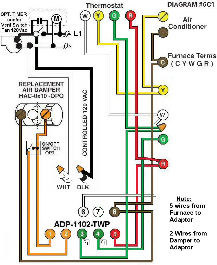
Diagram #6C1: Forced Air Furnace having a Replacement Air Supply Duct together with and Exhaust Fan controlled by a designated Ventilation Switch and/or Bathroom Timer
- Use Replacement Air Control Damper (Power Open) – (HAC-0x10-OPO)
- Ventilation Switch and/or Bathroom Timer to supply Controlled 120Vac to Furnace area
- Relay Adaptor (ADP-1102-TWP) to function as a control center
OPERATION:
- Replacement Damper opens to provide fresh air during the ventilation and/or heating cycle
- Ventilation Switch and/or bathroom timer turns on Ventilation Fan, opens Replacement Air Damper and turns on Furnace Fan simultaneously
- Optional Switch (i.e. toggle switch, timer, de-humidistat) connected to Adaptor 1 and 2 allows full control of the Replacement Air Damper to open as required
N.B. Replacement Air Damper is not affected by the ‘Manual’ setting of the Furnace Fan.
Also the Air Conditioner is not affected by the use of this Wiring System.