
Forced Air Furnace having a Replacement Air Supply Duct controlled by a designated Ventilation Switch and/or Bathroom Timer and a Kitchen Exhaust Fan:
#8B8. Forced Air Furnace with Power Close Replacement Air Damper (HAC-0x10-OPC) and Two Exhaust/Ventilation Fans that use Two Adaptors (ADP-1101-05A) and (ADP-0242-05A) to Open Replacement Air Damper with Exhaust/Ventilation Fans and also opens during Furnace firing.
HMI Hoyme Manufacturing Inc. Special Note: Circuits are colored for clarification only and are not necessarily those found in actual installations. Combustion Air Damper Wires, however, are colored as shown.
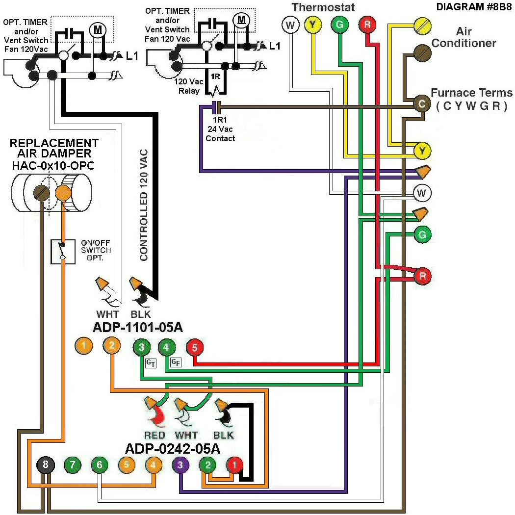
Diagram #8B8: Forced Air Furnace having a Replacement Air Supply Duct controlled by a designated Ventilation Switch and/or Bathroom Timer and a Kitchen Exhaust Fan.
- Use Replacement Air Control Damper (Power Close) HAC-0x10-OPC
- Ventilation Switch and/or bathroom timer to supply controlled 120Vac to Furnace area
- 24Vac dry contact switch points close when kitchen Exhaust Fan is operating
- Relay adaptors (ADP-1101-05A) and (ADP-0242-05A) to function as control centers or use (ADP-1103-TW5)
OPERATION:
- Replacement Damper opens to provide fresh air during the heating cycles.
- Ventilation switch and/or bathroom timer turns on Ventilation Fan, opens Replacement Air Damper and turns on Furnace Fan simultaneously.
- Kitchen Exhaust Fan closes 24Vac contact points, opens Replacement Air Damper and turns on Furnace Fan simultaneously.
- Damper will remain closed during manual Furnace Fan operation.
- Optional Switch (i.e. toggle switch) allows full control of the Replacement Air Damper to open separately provided it is a Power Close type Damper.
Note: This installation does not interfere with the normal operation of the heating cycle of the Furnace or the cooling cycle of the Air Conditioner.