
Two 120Vac Vent Switches, two Adaptors an 1101-05A and an 1102-TWP, a Replacement Air Damper, Power Close, opens during firing:
#6A4. Two 120vac Separate Ventilation Fans, Two Adaptors (ADP-1101-05A) and (ADP-1102-TWP), One Power Close Replacement Air Damper (-PC) Opens During Furnace Firing.
HMI Hoyme Manufacturing Inc. Special Note: Circuits are colored for clarification only and are not necessarily those found in actual installations. Combustion Air Damper Wires, however, are colored as shown.
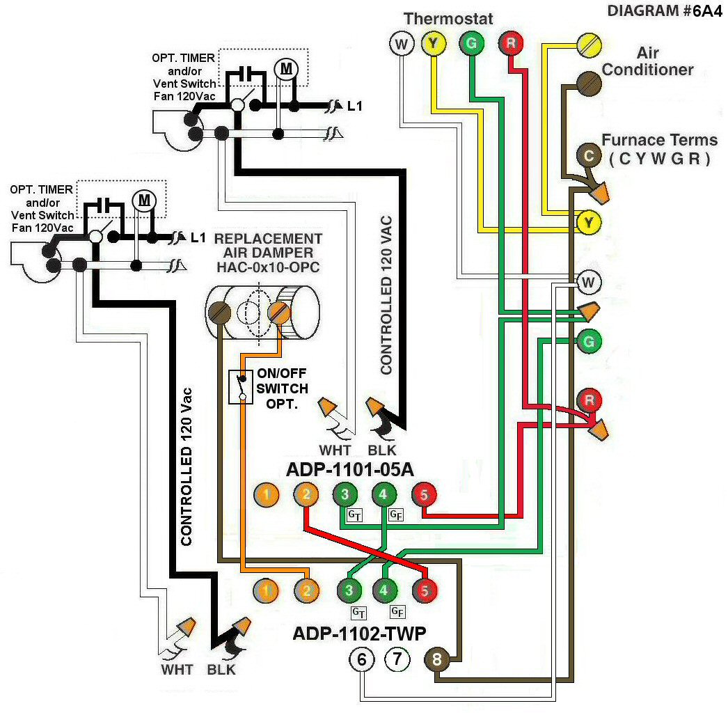
Diagram #6A4: Forced Air Furnace having one Replacement Air Supply Duct together with two Exhaust Fans controlled by two Relay Adaptors one being the (ADP-1101-05A) and the other being the (ADP-1102-TWP).
- A Replacement Air Control Damper, Power Close (HAC-0x10-OPC)
- Two Ventilation Switches to supply Controlled 120Vac to furnace area
- Two Relay Adaptors (ADP-1101-05A) and the other the (ADP-1102-TWP) Both function as a control centers to actuate the Replacement Air Damper from the Thermostat or by either Ventilation Switch
OPERATION:
- Replacement Damper opens during Furnace firing
- Either Ventilation Switch simultaneously turns on the Exhaust Fan, opens the Replacement Air Damper and turns on the Furnace Fan
- Optional Switch (i.e. Toggle Switch) allows full control of the Replacement Air Damper to open separately provided it is a Power Close (PC) type Damper
(For Power Open Damper see Diagram #6A5)
N.B. Replacement Air Damper is not affected by the ‘Manual’ setting of the Furnace Fan nor is the Air Conditioner affected in any way.