
Two Replacement Fresh Air Supply Ducts with Dampers, Exhaust Fan and Vent Switch:
#6B1. Ventilation Switch and Large Exhaust Fan, Two Replacement Fresh Air Supply Ducts with Two Power Open Air Dampers (-PO), Both Dampers Open for Large Exhaust Fan, One Damper Opens during Furnace firing.
HMI Hoyme Manufacturing Inc. Special Note: Circuits are colored for clarification only and are not necessarily those found in actual installations. Combustion Air Damper Wires, however, are colored as shown.
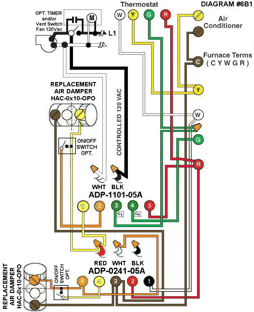
Diagram #6B1: One Forced Air Furnace having two Replacement Air Supply Ducts, two Fresh Air Dampers together with a large Exhaust Fan, a designated Ventilation Switch and/or Timer.
- Two Replacement Air Control Dampers (HAC-0x10-OPO) (Power Open)
- Ventilation Switch and/or timer to supply Controlled 120Vac to Furnace area
- (ADP-1101-05A) opens both Fresh Air Dampers when operating a large Exhaust Fan
- (ADP-0241-05A) opens only one Fresh Air Damper when Furnace is firing
OPERATION:
- Only One Fresh air Damper opens during Furnace firing
- Ventilation Switch and/or timer simultaneously turns on the Ventilation Fan, the Furnace Circulation Fan and opens both Fresh Air Dampers
- Optional Overriding Toggle Switch (connected to one damper only) causes both Fresh Air Dampers to open as required
N.B. Replacement Air Dampers are not affected by the ‘Manual’ setting of the Furnace Fan.