
Installation instructions – Printer friendly (pdf)
RADP-0241-S10A – Information Page
Installation Instructions for HMI HOYME RADP-0241-S10A
24Vac Controlled Voltage – Switches 24Vac and/or 120Vac Circuits
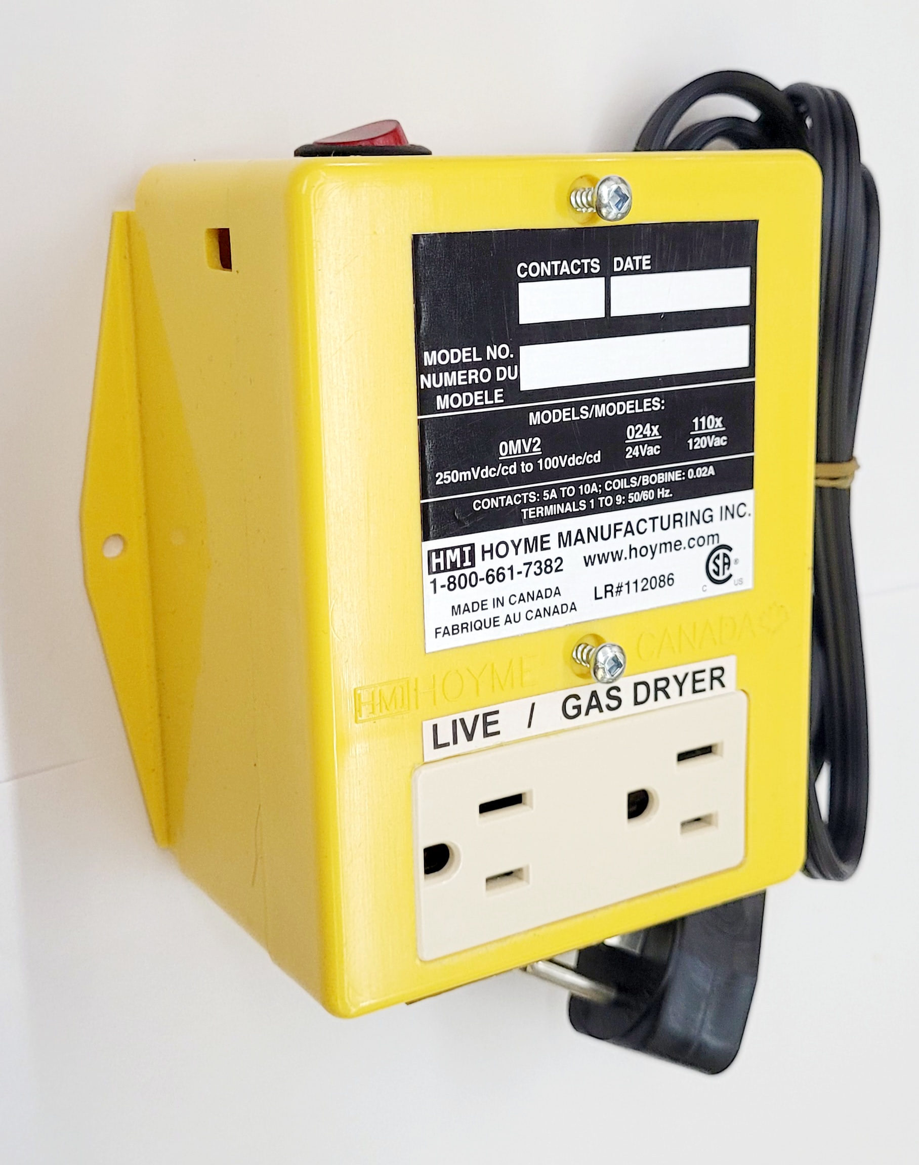
- 4” x 5” x 2 ½” (101 x 127 x 64 mm)
- Split Duplex Receptacle – Interlocked to a Gas Dryer/Damper Combination
- This interface Adaptor RADP-0241-S10A is an interlocking control device to safely supply fresh air for a dryer /damper /furnace combination
- The Adaptor has a manual red light switch that, when turned on, the fresh air damper opens proving its position prior to gas dryer operation (Interlocked)

Installation of this Adaptor shall be in accordance with the requirements of the authorities having jurisdiction
Refer also to HOYME Installation Instructions: Combustion Inlet Air Control Damper, Series HOM-SF1 and SF2; Replacement/Ventilation Air Control Damper, Series – HAC/MAC-0x11-SPC, HAC/MAC-0x10-SPO
This Adaptor may be interlocked to dampers:
- HOM-0x11-SF1
- HOM-0x12-SF2, secondary circuit
- HAC/MAC-0x11-SPC
- HAC/MAC-0x10-SPO
- This Adaptor may also be interconnected to simultaneously turn on a Furnace Circulation Fan and to Open an HAC replacement Air Damper, if used, on a furnace return plenum
- Damper(s) remain Open until the Red Light Switch is manually turned Off
- Fitness of this Adaptor/Damper combination to satisfy air supply requirements for fuel fired appliances during operation of the interconnected exhaust fan(s) shall be investigated by the enforcing authorities.
Air intake duct installation shall be in accordance with: In Canada – CAN/CSA B149 & B139; In the USA -ANSI NFPA 2006, ANSI Z223.1 and/or local codes including local codes relating to ventilation air duct installation.
I.D.: RADP-0241-S10A
- 1 Relay SPDT: Coil,.02A, 24Vac,Points,120Vac-10A
- 1 Relay DPDT: Coil,.02A, 24Vac, Points-24Vac- 5A
- Coils are connected in parallel to act as one relay
- 1 Split Duplex Receptacle: “LIVE”/”GAS DRYER”
- 1 Red Light “on/off” Switch
- 5’ – 3C Electric Cord with 90 degree plug-in
Notes: Refer to local and applicable codes, always conduct a thorough check-out after Installation is complete, affix appropriate labels and follow Instructions and warnings on each label
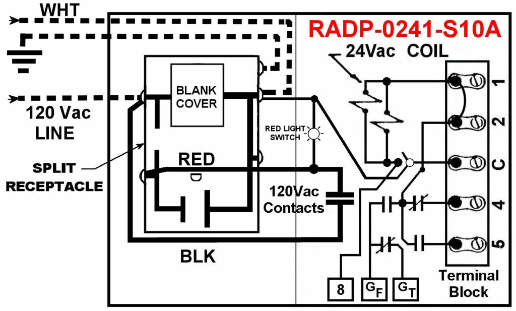
1. Dampers HOM-0x11-SF1 or MAC-0x11-SPC used for air supply to the Gas Dryer Only:
- Mount the Adaptor near the Gas Dryer for ease of Red Light Switch operation and near the 120Vac outlet that was used for the dryer.
- Use 2C-18Ga electrical wire to connect Damper terminals #4(common) and #5(live) to 24Vac supply. If using the heating appliance transformer, check transformer capacity
- Run 4C-18Ga. electric wire from the Damper to the Adaptor and connect as follows:
- Connect HOM/MAC Damper #4 to RADP #3(C)
- Connect HOM/MAC Damper #3 to RADP #8
- Connect HOM/MAC Damper #2 to RADP #1
- Connect HOM/MAC Damper #1 & #5 to RADP #2
- Turn on the electric power to the Damper causing the damper to close.
- Plug the Adaptor cord into the 120Vac outlet
- Plug the dryer cord into the ‘GAS DRYER’ side of the Adaptor Receptacle
- Turn on the Adaptor Red Light Switch. The Fresh Air Damper(s) will Open and the Gas Dryer is ready to be set for its operation
- Damper Opens for the drying cycle
- After the drying cycle is complete, turn the Red Light Switch off and the damper will Close
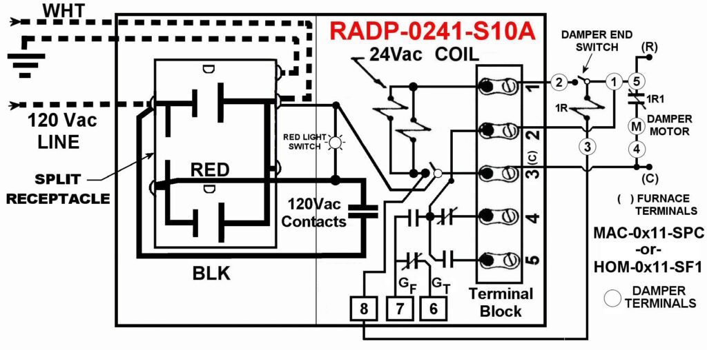
2. Damper HOM-0x12-SF2 used for the DUAL PURPOSE of supplying combustion air to both a heating appliance and to a Gas Dryer:
- Mount the Adaptor next to the Gas Dryer for ease of Red Light Switch operation and near the 120Vac outlet that was used for the dryer
- Turn off the appliance power to the HOM-0x12-SF2 Combustion Air Damper
- Run a 4C-18Ga electric wire along the gas line from the Heating Appliance electrical circuit to the RADP-0241-S10A Adaptor
- Connect the secondary circuit of the HOM Combustion Air Damper, the Adaptor and the Heating Appliance as follows:
- Connect HOM Damper #6 to Adaptor #2 and to the Heating Appliance ‘R’ (24Vac);
- Connect HOM Damper #7 to Adaptor #1;
- Connect HOM Damper #8 to Adaptor #8
- Connect Adaptor #3(C) to the Heating Appliance ‘C’ or to a ground screw.
- Turn on the electric power to the heating appliance. The Combustion Air Damper will Close
- Plug the Adaptor cord into the 120Vac outlet
- Plug the dryer cord into the ‘GAS DRYER’ side of the Adaptor Receptacle
- Turn on the Adaptor Red Light Switch. The Combustion Air Damper will Open and the Gas Dryer is ready to be set for its operation
- After the drying cycle is complete, turn the Red Light Switch off and the damper will Close
Note: Confirm HOM-SF2 Damper is properly working with primary furnace before connecting to the Gas Dryer. Refer to the Installation Instructions supplied with the Combustion Air Control Damper to confirm its proper operation.
3. When a heating system is equipped with a REPLACEMENT AIR SUPPLY DUCT leading into the return plenum, the Furnace Circulation Fan may be turned on to assist air movement to the dryer:
- For thermostats having an ‘automatic/manual’ fan switch:
- Disconnect thermostat wire from furnace ‘G’ and connect to Adaptor #6(Gt)
- Connect Adaptor #7(Gf) to furnace ‘G’
- Turn on the Adaptor Red Light Switch. The air supply damper will open, the furnace circulation fan will run and the Gas Dryer is ready to be programmed for its operation
- After the Gas Dryer has finished its cycle, turn the Adaptor Red Light Switch off. The furnace circulation fan will stop and the air supply Damper will close
4. A REPLACEMENT AIR CONTROL DAMPER HAC-0x10-OPO/PC on a fresh air duct leading into the return plenum may be used provided it is interconnected to open simultaneously with the furnace circulation fan when the Red Light Switch is turned on:
- For the HAC damper Power Open type:
- Connect one HAC damper wire to ‘C’ or ground screw on the furnace
- Connect the other HAC damper wire to Adaptor #5
- For the HAC damper Power Close type:
- Connect one HAC damper wire to ‘C’ or a ground screw on the furnace
- Connect the other HAC damper wire to Adaptor #4
5. If HAC Damper to also open during the firing cycle of the furnace, go to Installation Instructions on the Adaptor RADP-0242-S10A
RADP-0241-S10A – Information Page
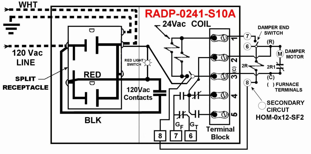
For further wiring information. please refer to the colored wiring diagrams supplied
Schematic Wire Diagram of RADP-0241-S10A – Includes Red Light On/Off Switch
Note: This marking is also on the cover of the Adaptor Unit and also on the label to be placed on the Appliance
For more information, please contact HMI HOYME Manufacturing Inc. 1-800-661-7382
Installation instructions – Printer friendly (pdf)
RADP-0241-S10A – Information Page