
Installation instructions – Printer friendly (pdf)
ADP-1101-05A – Information Page
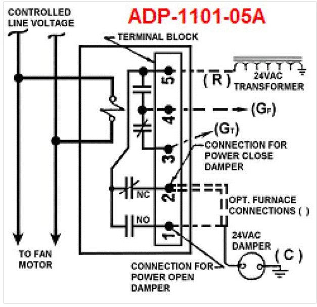
Installation Instructions for HMI Hoyme Adaptor-1101-05A – 120Vac Controlled Line Voltage to Switch 24Vac
- 4” x 5” x 2 1/2” (101 x 127 x 64 mm)
- Relay Coil – 120Vac. Contact Points – 24Vac – 5 Amps
- Installation Of This Adaptor Shall Be In Accordance With The Requirements Of the Authorities Having Jurisdiction
- Refer also to HOYME Installation Instructions – Combustion Inlet Air Control Damper, Series HOM; Replacement/Ventilation Air Control Damper – HAC; and ADP- 0241- 05/10A

- This Adaptor is an automatic 24Vac switch with a 120Vac coil to actuate a 24Vac motorized inlet damper for replacement or ventilation air
- By connecting the Adaptor Relay Coil to the controlled line voltage of an Exhaust Fan, clothes dryer , bathroom or kitchen fan, the inlet damper will open when turning on the appliance Exhaust Fan
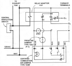
- A 120Vac de-humidistat or timer can also actuate the fan and damper. If the Furnace Circulation Fan is required to run simultaneously to the Exhaust Fan and an open inlet damper, use optional connections to the furnace shown on the schematic diagram
- Fitness of this Adaptor/Damper combination to satisfy air supply requirements for fuel fired appliances during operation of the interconnected Exhaust Fan(s) shall be investigated by the enforcing authorities
- Air Intake Duct installation shall be in accordance with: In Canada – CAN/CSA B149 & B139; In the USA – ANSI/NFPA 54, 2006, ANSI Z223.1 and/or local codes including local codes relating to ventilation air duct installation.
- ADP-1101-05A comes with 1 – DPDT Relay
- Coil – 120Vac Points – 24Vac – 5 Amps
- One adaptor is required for each Exhaust Fan controlling a Motorized Fresh Air Damper
- When there is more than one Exhaust Fan per Inlet Damper, Adaptor 24Vac terminals must be connected: 1) in series to each other for a Power Close Damper, 2) in parallel to each other for a Power Open Damper
- Adaptor line voltage leads, connected to the Exhaust Fan controlled line, shall be suitably cabled, fastened and enclosed in suitable raceways
- Refer to local and applicable codes
- Always conduct a thorough check-out after installation is complete
- Affix appropriate labels and follow instructions and warnings on each label
Installation Instructions for ADP-1101-05A
- Install Motorized Air Control Damper as per instructions supplied with it.
- Satisfactory operation of the Inlet Damper is recommended before interconnecting Adaptor
- Turn off electrical power supply to appropriate appliance(s)
- Connect Adaptor line voltage leads to the controlled Exhaust Fan circuit as per wiring diagram- Follow applicable codes
- Connect 24Vac wire to Adaptor terminal 5, and connect Adaptor terminal 2 to Inlet Air Damper, Power Close type. If Inlet Damper is Power Open type, then connect to Adaptor terminal 1 instead of 2
- Connect common side of 24Vac transformer (C) to remaining side of Damper Motor (See damper wiring diagram for motor circuit)
- Turn on electrical line power to appliance(s). If damper is a Power Open type, it will remain closed at this time. If damper is a Power Close type, it will close at this time
- Turn on Exhaust Fan Switch.
- Exhaust Fan will run and inlet damper will open simultaneously.
Note: If Furnace Fan is required to run during Exhaust Fan cycle, connect Adaptor 4 to Furnace (GF) (G may vary on different furnaces) connect Thermostat (GT) to Adaptor 3
SCHEMATIC WIRE DIAGRAM of Adaptor 1101
Used As A Switch To Control A 24Vac Inlet Damper and/or a Furnace Fan
Relay Coil: 120 ; Points 24Vac: 05A
Note: This marking is also on label to be affixed adjacent to appliance wiring diagram.
Additional wire shall be of the same size as originally used when completing electric circuits
 | 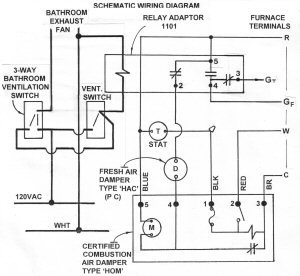 |
| Typical Schematic Wiring Diagram of ADP-1101 connects to a Certified Combustion Air Damper, a Fresh Air Inlet Damper & Furnace Circulation Fan Switch | Controlled by a 3-Way Ventilation Switch |
For more information, please contact HMI HOYME Manufacturing Inc. @ 1-800-661-7382
Installation instructions – Printer friendly (pdf)
ADP-1101-05A – Information Page