
Combustion Air Damper and Replacement Air Damper (Power Close):
#3. Combustion Air Damper (HOM-0x11-SF1) Interlocked to a Furnace and interconnected to a Power Close Fresh Air Damper (HAC-0x10-OPC).
HMI Hoyme Manufacturing Inc. Special Note: Circuits are colored for clarification only and are not necessarily those found in actual installations. Combustion Air Damper Wires, however, are colored as shown.
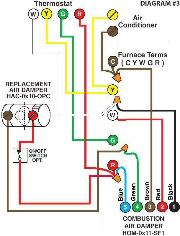
Diagram #3: Forced Air Furnace having a Combustion Fresh Air Supply Duct and a Replacement Air Supply Duct.
- Combustion Air Damper (HOM-0x11-SF1)
- Replacement Air Damper. Power Close Damper is required. (HAC-0x10-OPC )
OPERATION:
- Replacement Air Damper is inter-connected to the Combustion Air Damper which is interlocked so that both Dampers open during the heating cycle and close when the fire stops
- Optional switch (i.e. toggle switch, timer, de-humidistat) allows full control of Replacement Air Damper to open provided it is the Power Close (PC) type
N.B. Replacement Air Damper is not affected by the ‘Manual’ setting of the Furnace Fan.