
Combustion Air Damper with Heat Limit Switch:
#1B. DHW with Heat Limit Switch (HLS-1100) Interconnected to a Combustion Air Damper (HOM-0x11-SF1), No Furnace.
HMI Hoyme Manufacturing Inc. Special Note: Circuits are colored for clarification only and are not necessarily those found in actual installations. Combustion Air Damper Wires, however, are colored as shown.
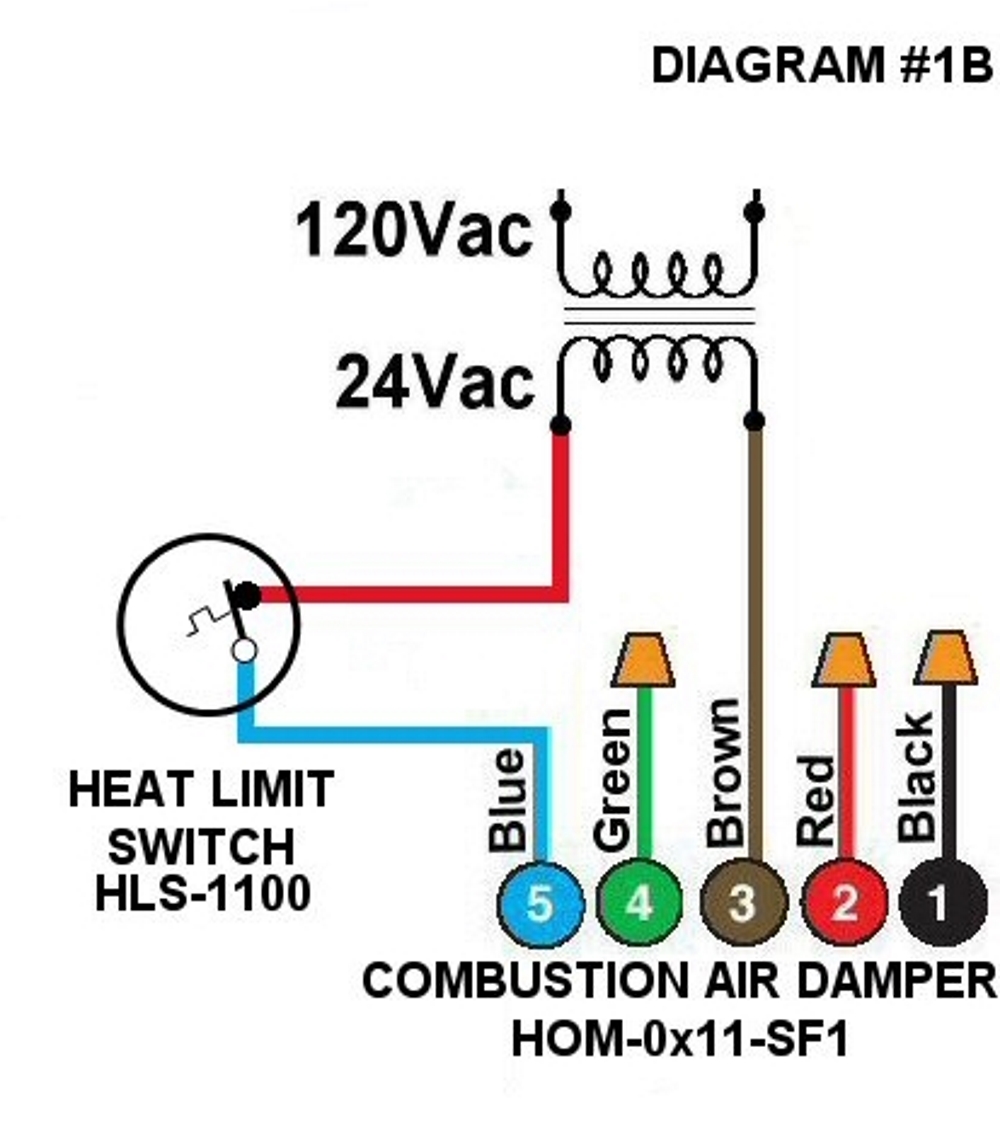
Diagram #1B: A Domestic Hot Water tank using a Combustion Air Supply Duct.
- Combustion Air Damper (HOM-0x11-SF1) for one Furnace or Boiler
- Optional Heat Limit Switch (HLS-1100) that opens on temperature rise
OPERATION:
Combustion Air Damper connected in series to a continuous 24Vac power supply and a Heat Limit Switch. Heat Limit Switch attached to Hot Water Tank Flue stack. Combustion Air Damper opens with the sensing of a temperature rise of 130°F and closes when cooled down to 125°F.