
Hoyme-HAE-installation-instructions-residential – pdf
HAE – Product Information Page – pdf
HAE Commercial – Installation Instructions – pdf file
HMI Hoyme Manufacturing Inc.
Installation Instructions for the HOYME Air Exchanger (HAE)-HRV
A Furnace Fan Generated Air Exchanger (HRV) for the ‘Whole House as a System
100 CFM & 200 CFM MODELS
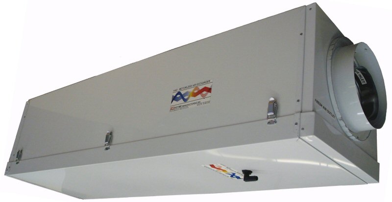
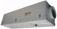 Inline Model HAE-1000-X00* | 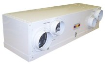 Offset Model HAE-1001-X00* |
 Interior View HAE-1000-X00* (Bottom) |
* Where ‘x’ = CFM x 100
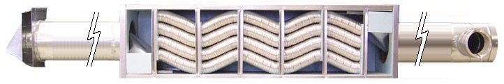
This Lab tested Air Exchanger (HAE) showed an apparent sensible effectiveness of over *10% higher than the conventional HRV, is low in maintenance, easy to install and provides a continual flow of fresh air even during long periods of extreme cold temperatures
*Based on tests done by National Research Council, Ottawa, 2014*
| Specifications: | Shipping Weight: |
| HAE-1000-100 – 14 ” x 13 ” x 50 “ HAE-1000-200 – 14 ” x 17 ” x 50 “ | Models: 100 ~34lbs.; 200 ~38lbs Installation Kits ~19lbs |
All Models Come with:
- Plastic Drain Hose ½” (#9) (15′)
- 24″ Mounting Brackets (#10) (x2)
- Add a matching Kit as shown on page 13, 14 or 15
- Installer is to supply ducting
- Numbered parts and assembly drawings are shown on page 12
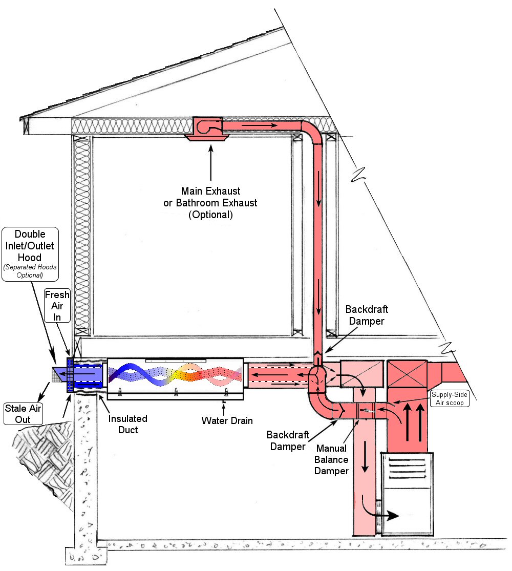
The Hoyme Air Exchanger (HAE)-HRV is a Heat Recovery Ventilator that distributes fresh/exhaust air to and from the ‘Whole House as a System’ by simply using the furnace fan – See page 11 (HAAS)
For maximum expected efficiency, the HAE-HRV is to be connected close to the furnace on both return and supply plenums with nothing in between except the appliance filter. If a 6″Ø Power Humidifier (PH) is mounted between the two plenums, the efficiency of the HAE can be maintained by adding a power open damper to the PH to open only during the humidifying cycle
The HAE operates continual, even during the defrosting cycle, making it ideal to vent bathrooms, kitchens & central vac systems through it – See page 16 for details.
 |
Installation Instructions:
- Read complete instructions before starting the installation of this product
- This installation shall be subject to the approval of the enforcing authorities
- Air supply and installation shall be in accordance with National Building Codes and/or Local Codes
- The HAE is designed for a Forced Air Furnace/Air Handling System preferably having a multi-stage motor running 24/7
SECTION “A”: – Inline Type HAE – HRV
- INLINE HAEs are not to be fastened directly to Connectors/Hoods. Use flex/rigid ducting instead
Models HAE-1000-100 and HAE-1000-200
- Select suitable location for the HAE making allowances for Plenum connectors, Ducting, and removal of the Bottom Inspection Pan
- Mount the HAE securely between or below the floor joists as shown using screws and two metal Mounting Brackets #10 supplied
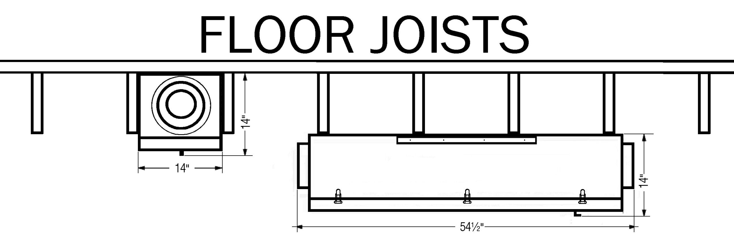 Mount the HAE to be level for water drainage and with the drain spout end of the HAE positioned closest to the return plenum. |
Double Plenum Connector #3
- Mount the Double Plenum Connector #3 to the horizontal return plenum and as close as possible to the furnace
- Cut the proper size hole in the plenum to match the diameter of the DPC plus ¼” for clearance
- Before mounting , turn the DPC so that the 5″ Ø/6 ” Ø elbow on the side of the DPC faces the supply plenum
- Also note the proper position for fastening the Shield #4 so that, when fastened, it will point in the same direction as the air flow in the return plenum
- The Shield is to help increase the flow of incoming air. Fasten the Shield in this position with three sheet metal screws
- Fasten the DPC to the return plenum with sheet metal screws using holes in the DPC collar for spacing.
Manual Air Balance Damper #5
- Mount the Manual Air Balance Damper to the supply plenum and as close as possible to the furnace
- Cut a 5/6″ Ø hole plus clearance to accept the diameter of the MABD
- Turn the MABD to a position for ease of adjusting the damper lever while at the same time noting the position to fasten the Scoop #5b so that it points against the air flow in the plenum. In this position more air will be directed to the HAE exhaust
- Fasten the Scoop in this position with 3 sheet metal screws
- Mount the MABD securely to the supply plenum with sheet metal screws using the holes in the MABD collar for spacing
About Rigid Ducting
- Using Rigid Ducting increases the efficiency of Air Flow plus it assists in draining any water that may accumulate.
- These Instructions, however, refer to the use of flex ducting
- Flex ducting is to be stretched and cut to length so that the maximum diameter of the ducting can be realized when installed
- Follow acceptable trade practices when installing, routing and connecting all duct work leaving it neat and tidy
NOTE: All 5/6″ Ø concentric ducting is not to be insulated . Outer Ducting between the HAE and the Plenum may not require insulation. All Outer Ducting between the HAE to the Outside Hood(s) requires insulation
Connect HAE to the Plenum Connectors
- Connect the Manual Air Balance Damper to the 5/6″Ø elbow of the Double Plenum Connector #3 by using the Aluminum Foil Ducting #8 supplied. Stretch, cut to length and fasten ducting into place. If the supplied Ducting #8 is too short, contractor is to supply longer ducting of equal or better quality
- Connect the Double Plenum Connector #3 to the HAE. First, insert the HAE Extension Sleeve #6a into the HAE and fasten into place with a sheet metal screw
- Stretch and cut both 5/6″ Ø and 8 ” Ø/9 ” Ø ducts to length to reach between the DPC and the HAE
- Fasten both ducts to the DPC with the inner duct to be connected first. The other ends of the ducts are to be connected to the HAE with the 5/6 ” Ø duct to be fastened to the Extension Sleeve #6a and the Outer Duct to be fastened directly to the HAE . Fasten and seal all connections
Outside Double Hood #2
7. Mount the Double Hood to the outside wall of the building above the level of anticipated snow. Make an opening in the outside wall large enough to match the diameter of the Hood plus extra room for ease of insulation and installation. Fasten into place with proper screws.
CONNECT DOUBLE HOOD #2 TO THE HAE
8. Insert the Extension Sleeve #6a into the HAE and fasten into place with a sheet metal screw. The Hood has an adjustable 5 “/6″ Ø sleeve that is to protrude far enough for ease of connecting the 5/6 ” Ø duct. Stretch both 5/6″ Ø ducting and the insulated 8 “Ø/9 ” Ø ducting to extend between the Hood and the HAE and cut to length. Fasten both ducts to the HAE with the inner duct to be connected first to the HAE Extension Sleeve #6a . The other ends of the ducts are to be connected to the Hood with the 5/6 ” Ø duct fastened to the adjustable sleeve and then the Insulated Duct fastened directly to the Hood.
½” Ø Plastic Drain Hose #9
- Connect the ½”Ø plastic hose #9 (supplied) to the drain spout and always position this hose lower than the bottom of the pan for draining water caused by the defrost cycle
- Provide a low spot in the hose to act as an air/water trap.
- Rigid copper tubing ½”Ø is often used for horizontal distances
* Ice forms in the HAE during cold weather but automatically defrosts during the heating cycle of the furnace.
Two Outside Hoods can be used to Replace the Double Hood
- Where it is advisable to use two Outside Hoods instead of the Double Hood, a Two- Hood Connector #2a is required
- Mount the THC securely and preferably close to the outside wall. Connect the THC to the HAE by first fastening the Extension Sleeve #6a to the HAE with a sheet metal screw.
- The 5/6″ Ø duct and the insulated 8 ” Ø/9 ” Ø duct is to be stretched and cut to length to reach between the THC and the HAE. Fasten both ducts to the HAE with the 5/6 ” Ø duct fastened to the Extension Sleeve #6a and the insulated duct to the HAE .
- The other ends of the ducts are to be connected to the THC
Two Outside Hoods #2b(5/6 ” Ø) #2c(6 ” Ø)
- Mount the Two Hoods on the outside wall 6’ apart and above the level of anticipated snow
- Proper sized holes plus clearances are required for the two hoods
- Mount and fasten the Hoods into place with proper screws
- Cut to size/length and connect two insulated ducts between the Two-Hood Connector and two Hoods
- Also insulate the Two-Hood Connector so that all ducting from the HAE to the outside wall is insulated
SECTION “B”: – Offset Type HAE
- Where space is limited, Offset
- Models HAE-1001-100, HAE-1001-200 plus two Hoods allow it to be placed in a variety of smaller places plus the availability of installation kits to match. See page 14 for available kits
- Select suitable location for the HAE while making allowances for Plenum Connectors, Ducting, and the removal of the Bottom Pan
- Mount the HAE securely, preferably to the floor joists, using screws and two metal Mounting Brackets #10 supplied
- Mount the HAE to be level for drainage and the drain spout end of the HAE to be positioned closest to the return plenum
Return Plenum Connecter #3a(6″ Ø)
- Mount the Return Plenum Connector 6″ Ø to the horizontal return plenum as close as possible to the furnace
- Cut the proper size hole in the plenum plus ¼” to accept the diameter of the RPC. Fasten the Shield #4 to the RPC with three sheet metal screws
- When mounting the RPC into the plenum, turn it so that the Shield will point in the same direction as the air flow in the plenum
- The Shield is to help increase the flow of incoming air. Fasten the RPC with sheet metal screws using holes in the collar for spacing
Manual Air Balance Damper (MABD) #5
- Mount the Manual Air Balance Damper to the supply plenum and as close as possible to the furnace
- Cut a 5/6″ Ø hole plus ¼” to accept the diameter of the MABD
- Turn the MABD to a position for ease of adjusting the damper lever while at the same time noting the position to fasten the Scoop #5b so that it points against the airflow in the plenum. More air will then be directed to the exhaust of the HAE
- Fasten the Scoop in this position with 3 sheet metal screws supplies
- Mount the MABD securely to the supply plenum with sheet metal screws using the holes in the MABD collar for spacing
Connecting MABD #5 to the HAE
- Connect the MABD to the HAE 5/6″Ø fixed sleeve located at the drain spout end of the HAE by using the Aluminum Foil Ducting #8 supplied. Stretch, cut to length and fasten ducting into place
- If Ducting #8 supplied is too short, Contractor is to supply ducting of equal or better quality
Connecting RPC #3a(6″Ø) to the HAE
- Connect the Return Plenum Connector #3a to the HAE 6″Ø fixed side sleeve at the drain spout end of the HAE using ducting supplied by the Contractor
- Insulated ducting is not required here
Outside Hoods #2b(5/6″Ø) #2c(6″Ø)
- Mount the Two Hoods to the outside wall 6’ apart and above the level of any anticipated snow
- Proper sized holes plus clearances are required to match the size of hoods.
- Mount and fasten the Hoods into place with proper screws
- Connect the Two Hoods to the HAE using proper sized Insulated Ducting
Follow acceptable trade practices when installing, routing and connecting all duct work leaving it neat and tidy, free from holes and away from excess heat.
Offset Type HAE with a Double Hood and a Double Hood Connector
- If a Double Hood (DH) #2 is used instead of the Two Outside Hoods, it is necessary to add an Offset Double Hood Connector [ODHC #2d 5/6 ” (8/9″ Ø)] to be placed and connected between the HAE and the DH
- Make only one opening in the outside wall above the level of any anticipated snow to accept the diameter of the Double Hood plus ¼” clearance
- Fasten the Hood into place with proper screws
- Install and fasten the ODHC#2d securely close to the Double Hood (DH) with the concentric ends facing the DH.
- Extend and fasten adjustable 5/6 ” Ø sleeve that is inside the DH to protrude far enough for ease of connecting the 5/6 ” Ø non-insulated duct
- Stretch both 5/6″ Ø ducting and the insulated 8 ” Ø/9 ” Ø ducting to extend between the DH and the ODH Connector and cut to length
- Fasten both ducts to the DH with the inner duct to be connected to the adjustable sleeve first.
- The other ends of the ducts are to be connected to the ODH Connector with the 5/6 ” Ø duct connected first
- Also insulate the ODHC
- .Connect the Offset Double Hood Connector to the sleeves of Offset HAE using proper length and size of Insulated Ducting
Follow acceptable trade practices when installing, routing and connecting all duct work
½” Ø Plastic Drain Hose #9
- The ½” Ø plastic hose #9 (supplied) is to be fastened to the drain spout and always kept lower than the bottom of the pan for draining water collected during the defrost cycle*
- Provide a low spot in the hose to act as an air/water trap
- Rigid copper tubing ½” Ø is often used for horizontal distances
* Ice forms in the HAE during cold weather but automatically defrosts during the heating cycle of the furnace.
 BALANCING AIR FLOW WITH THE MANUAL AIR BALANCE DAMPER |
A single Furnace Fan generates the movement of air in and out of the HAE to automatically Supply/exhaust air to the house where needed. Therefore, the main purpose of the Manual Air Balance Damper is not to balance the flow of air through the HAE but to control the amount of hot air that flows through HAE so as not to lose too much heat during the furnace firing cycle (de-icing cycle) and at the same time to allow enough hot air to heat the incoming air during the regular non-heating cycle.
Suggestion: Start by setting the Manual Air Balance Damper (#5 ) to be two-thirds open.
With the Furnace NOT FIRING but the Furnace FAN RUNNING for approximately five minutes, and any intermittent house exhaust fans turned off, adjust the Manual Air Balance Damper so that the following approximate temperatures can be obtained.
- If outside temperature is 0°C, then air entering the return plenum should be 18 to 20°C while the air leaving the HAE should read approximately 6 to 10°C
- If outside temperature is -30 to -35°C, then air entering the return plenum should read approximately 12 to16°C while the air leaving the HAE should read approx. 0°C to -6°C
These are typical installation readings.
With these settings in winter months, ice forms during the regular non-firing cycle and melts during the firing cycle. During the summer, the HAE works in reverse with the air conditioned air that is exhausted cools the incoming summer air
The ‘House As A System’ (HAAS)
Question: A single Furnace Fan moves air in and out of the HAE and ultimately to the whole house, but tests show there is more aircoming in through the HAE than is being exhausted? This appears to be an unbalanced system
Answer: If houses were perfectly sealed and free from any exhaust fans, air leakage included, then the amount of incoming air through the HAE and being circulated through the house would return in an equal amount to be exhausted through the HAE
The HAE would then appear to be a balanced system. One cubic foot of air in equals one cubic foot of air out. But all houses have some air leakage, plus air being exhausted by separate fans. This results in less air being returned to the HAE for exhausting. Since the HAE has less air being exhausted than there is air entering, the HAE itself does show an imbalance of air flow. But when we consider the ‘House as a System’ and factor in air that is lost through leakage and exhaust fans, it follows that using the HAE, generated by a single furnace fan, allows the ‘House as a System’ to adjust and to maintain a more natural balanced condition
The defrost cycle of the HAE is also automatic that occurs only during the heating cycle of the furnace. There is no ‘down time’ for defrosting which will then actually allow a continual flow exhausting of air even during extreme cold temperatures. This means that it is ideal for venting bathrooms, kitchens and central vacuum systems through the HAE
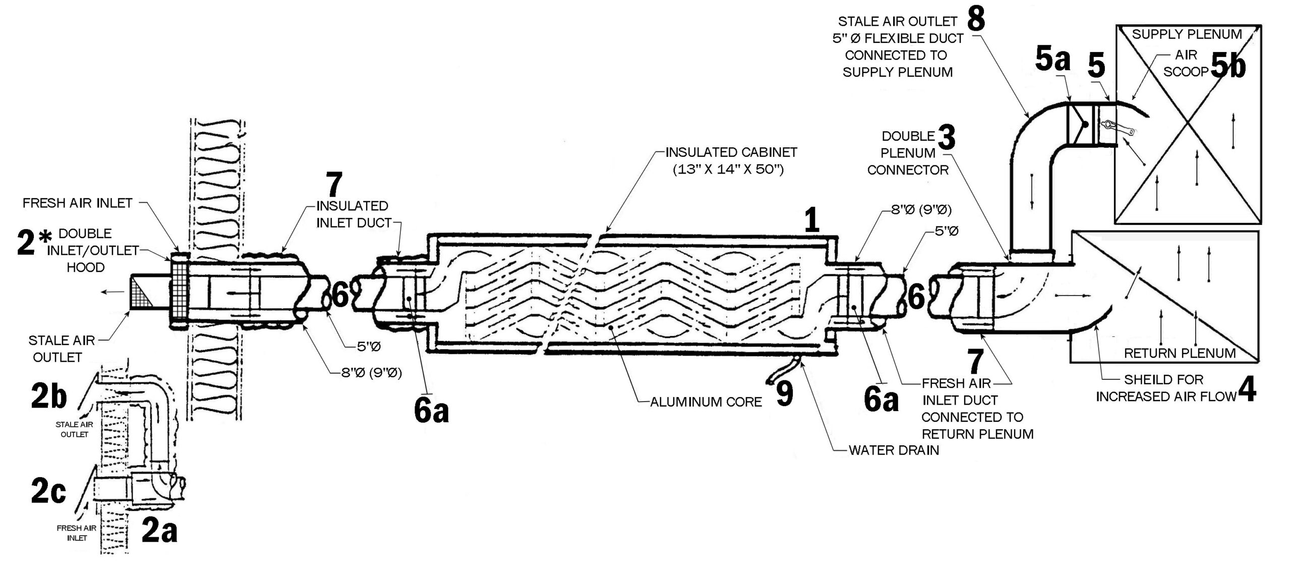 Typical Installation of the Inline Hoyme Air Exchanger HAE-1000-x00 |
Part Numbers include:
#1 – HAE-100x-x00 Air Exchanger. 100 ( W=14″, H=13″, L=50″) -or- 200 (W=14″, H=17″, L=50″).
#2 – 8″Ø (9″Ø) Double Hood (INLET & EXHAUST).
#2a – 8″Ø (9″Ø) Two-Hood Connector
#2b – 8″Ø (9″Ø) Offset Double-Hood Connector
#3 – 8″Ø (9″Ø) Double Plenum Connector, (Supply & Return)
#4 – Air Flow Shield
#5 – 5″Ø (6 “Ø) Manual Air Balance Damper
#5a – 5″Ø (6 “Ø) Backdraft Damper
#5b – AIR SCOOP
#6 – 5″Ø (6 “Ø) Npn-Insulated Ducting, 25 FT. Cut to Length as Required
#6a – 5″Ø ( 6 “Ø) HAE Extension Sleeve
#7 – 8″Ø (9″Ø) Insulated Flex Ducting, 25 FT. Cut to Length as Required
#8 – 5″Ø (6 “Ø) Flexible Aluminum Foil Ducting X 4 FT
#9 – ½ “Ø Plastic Drain Hose X 15 FT
#10 – Mounting Brackets – 24″ X 2
#11 – 8″Ø (9″Ø) Duct Clamps X 4; 5″Ø (6 “Ø) Duct Clamps X 6 (OPTIONAL)
HAE RESIDENTIAL MODEL
HAE-1000-x00 – Inline Type
Includes ITEMS #1, 9, & 10
#1 – HAE-1000-x00 Air Exchanger
100 model (W=14″, H=13″, L=50″)
200 model (W=14″, H=17″, L=50″).
#9 – ½ ” Plastic Drain Hose X 15 FT
#10 – Mounting Brackets X 2
HAE Kits for HAE-1000-x00 Inline Type
The IKIT-100 & IKIT-200 Includes:
- #2 – HAE Double Hood – All Weather 8″Ø (9″Ø for 200 model)
- #3 – HAE Double Plenum Connector , 8″Ø (9″Ø for 200 model)
- #4 – Air Flow Shield 8″Ø (9″Ø for 200 model)
- #5 – HAE Manual Air Balance Damper, 5″Ø(6″Ø)
- #5b – Air Flow Scoop , 5″Ø(6″Ø)
- #6a – HAE Extension Sleeve, 5″Ø (6″Ø)X 4″L (x2)
- #8 – Flexible Aluminum Foil Duct, 5″Ø, (4′)
HAE-1000-100 – Hoyme Air Exchanger Kit – HAE-iKit-100 – pdf
HAE-1000-200 – Hoyme Air Exchanger Kit – HAE-iKit- 200 – pdf
The IKIT-101 & IKIT-201 Includes
- #2a – HAE Two Hood Connector, 9″Ø
- #2b – All Weather Outlet Hood 5″Ø, VELCRO (6″Ø for 201 model)
- #2c – All Weather Inlet Hood 6″Ø
- #3 – HAE Double Plenum Connector, 8″Ø (9″Ø for 201 model)
- #4 – Air Flow Shield 8″Ø (9″Ø for 201 model)
- #5 – HAE Manual Air Balance Damper, 5″Ø (6″Ø for 201 model)
- #5b – Air Flow Scoop, 5″Ø (6″Ø for 201 model)
- #6a – HAE Extension Sleeve, 5″Ø X 4″L (x2) (6″Ø for 201 model)
- #8 – Flexible Aluminum Foil Duct, 5″Ø, (4′) (6″ for 201 model)
HAE-1000-100 – Hoyme Air Exchanger Kit – HAE-iKit- 101 – pdf
HAE-1000-200 – Hoyme Air Exchanger Kit – HAE-iKit- 201 – pdf
“HAE-1001-x00” – Offset Type
Includes ITEMS #1, 9, & 10
#1 – HAE-1001-x00 Air Exchanger
100 model (W=14″, H=13″, L=50″)
200 model (W=14″, H=17″, L=50″)
#9 – ½ ” Plastic Drain Hose X 15 FT
#10 – Mounting Brackets X 2
HAE Kits for HAE-1001-x00 Offset Type
The OKIT-101 & OKIT-201 Includes
- #2b – All Weather Outlet Hood, VELCRO, 5″Ø (6″Ø for 201 model)
- #2c – All Weather Inlet Hood, 6″Ø
- #3a – Return Plenum Connector 6 “Ø
- #4 – Air Flow Shield 6″Ø
- #5 – HAE Manual Air Balance Damper, 5″Ø(6″Ø for 201 model)
- #5b – Air Flow Scoop, 5″Ø(6″Ø for 201 model)
HAE-1001-100 – Hoyme Air Exchanger Kit – HAE-oKit- 101 – pdf
HAE-1001-200 – Hoyme Air Exchanger Kit – HAE-oKit- 201 – pdf
The OKIT-100 & OKIT-200 Includes
- 2 – HAE Double Hood – All Weather, 8″Ø (9″Ø for 200 model)
- #2d – HAE Offset Double Hood Connector, 8″Ø (9″Ø for 200 model)
- #3a – Return Plenum Connector 6″Ø
- #4 – Air Flow Sheild 6″Ø (7″Ø for 200 model)
- #5 – HAE Manual Air Balance Damper, 5″Ø (6″Ø for 200 model)
- #5b – Air Flow Scoop, 5″Ø(6″Ø for 200 model)
HAE-1001-100 – Hoyme Air Exchanger Kit – HAE-oKit- 100 – pdf
HAE-1001-200 – Hoyme Air Exchanger Kit – HAE-oKit- 200 – pdf
Adding an Exhaust Fan(s) – from Bathroom, Kitchen and other Areas
HAE – To Add Exhaust Fan
- Install a Y-duct( 5″ Ø x 5″ Ø x 4 ” Ø) inline between the 5″ Ø Backdraft Damper (#5a) connected to the Manual Air Balance Damper (#5b ) on the supply plenum and the 5″ Ø side of the Double Plenum Connector (#3) as shown in the illustration
- Install 4 ” Ø back draft damper inline the 4 ” Ø side of the Y-duct
- Connect the exhaust fan duct to 4 ” Ø Y- duct as shown
Additional Exhaust Fans can also be installed in the same way each with their own Y-duct and 4 ” Ø back draft damper.
HAE – Installation Instructions – pdf
HAE – Product Information Page
HAE Commercial – Installation Instructions – pdf