
Installation instructions – Printer friendly (pdf)
ADP-1101-10AS – Information Page
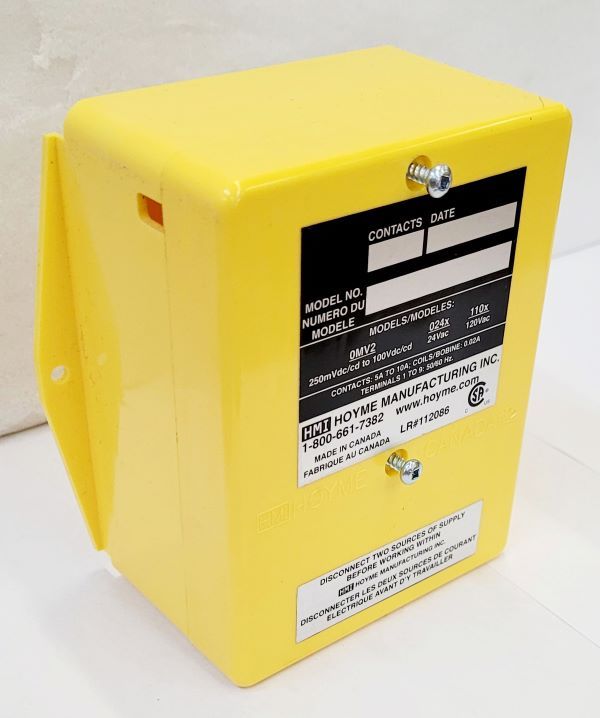
Installation Instructions for HMI HOYME Adaptor-1101-10AS
- 4” x 5” x 2 1/2″ (101 x 127 x 64 mm)
- Controls Two Separate Exhaust Fans to Operate Non-Concurrently while the Furnace Circulation Fan and Fresh Air Damper operate for either Exhaust Fan
- Installation of this Adaptor Shall be in accordance with the requirements of the authorities having jurisdiction.
- Note: If the replacement Air Damper is to also Open during the firing cycle of the furnace, replace ADP-1101-05A with ADP-1102-TWP

Refer also to HMI HOYME Installation Instructions for:
- Air Control Damper: HAC-0x10-OPO/PC
- Relay Adaptors: ADP-1101-05A, ADP-1102-TWP, ADP-1103-TWP & ADP-1102-TW5
This Adaptor ADP-1101-10AS is an automatic control switch designed to operate with ADP-1101-05A or with ADP-1102-TWP:
- Connect to two Exhaust Fans, either one to operate from its own Exhaust Fan Switch but is interlocked to prevent the two Exhaust Fans from operating at the same time
- Simultaneously turn on the furnace Circulation Fan for either Exhaust Fan
- Simultaneously open a Replacement/Ventilation Damper (if used) for either Exhaust Fan
- Fitness of this Adaptor/Damper combination to satisfy air supply requirements for fuel fired appliances during operation of the Interconnected Exhaust Fan(s) shall be investigated by the enforcing authorities
- Air Intake Duct installation shall be in accordance with: In Canada- CAN/CSA B149 & B139, the USA – ANSI/NFPA 54, 2006, ANSI Z223.1 and/or local codes including local codes relating to Ventilation Air Duct Installation
- I.D: ADP-1101-10AS comes with:
- two relays with coils in parallel and therefore operate as one relay:
- DPDT- Coil – 120Vac. Points – 24Vac- 5 Amps or
- SPDT – Coil-120Vac. Points 120Vac -10 Amps
- Adaptor line voltage leads, connected to the Exhaust Fan controlled line, shall be suitably cabled, fastened and enclosed in suitable raceways.
- Always refer to local and applicable codes.
- Always conduct a thorough check-out after installation is complete.
- Affix appropriate labels and follow instructions and warnings on each label.
Note: Adaptor ADP-1101-10AS requires interconnection to either ADP-1101-05A or ADP-1102-TWP. Use ADP-1102-TWP in place of ADP-1101-05A if Replacement/Ventilation Damper is required to also open during furnace firing. Refer to appropriate installation instructions for each. Follow applicable codes.
- Turn off electrical power supply to affected appliance(s)
- Choose an appropriate location for the two Adaptors and fasten into place with screws
- 120Vac Electrical connections to ADP-1101-10AS and to the Exhaust Fan circuits
- PRIMARY Exhaust Fan Circuit: Connect the controlled 120Vac from the Primary Exhaust Fan Switch to the fan and to the Black and White wires of the ADP-1101-10AS
- SECONDARY Exhaust Fan Circuit: Connect the 120Vac live wire directly to one of the RED wires of ADP-1101-10AS and connect the other RED wire directly to the supply side of the Secondary Vent Fan Switch which controls power to the Secondary Exhaust Fan
- 120Vac Electrical Connections for ADP-1101-05A or ADP-1102-TWP to the Controlled side of the SECONDARY Vent Fan Switch
- Connect the 120Vac controlled side of the Secondary Vent Fan Switch to the Secondary Vent Fan and to the Black and White wires of ADP-1101-05A (-TWP)
- 24Vac Electrical connections to ADP-1101-10AS together with ADP-1101-05A (-TWP) which controls the furnace fan and a Power Open/ Power Close (PO/PC) Fresh Air Damper (if used)
- Connect thermostat G to 3(Gt) of ADP-1101-10AS
- Connect 4(Gf) of ADP-1101-10AS to 3(Gt) of ADP-1101-05A (-TWP)
- Connect 4(Gf) of ADP-1101 (-TWP) to Furnace G. Connect terminal 5 of both Adaptors to furnace R
- If an Inlet Fresh Air Damper is used (PO/PC), connect one damper wire to furnace Terminal C.
- For a PO damper, connect the other damper wire to Terminal 1 of both Adaptors
- For a PC damper, connect the other wire to 2 of ADP-1101-05A (-TWP). Disconnect Terminal 5 of ADP-1101-05A (-TWP) from terminal 5 of ADP-1101-10AS and reconnect to Terminal 2 of ADP-1101-10AS
- Turn on electrical line power to appliance(s). If damper is a Power Open type, it will remain closed at this time. If damper is a Power Close type, it will close at this time
- Turn on the Secondary Exhaust Fan Switch. The Secondary Exhaust Fan, the Furnace Circulation Fan and the Inlet Damper (if used) will all operate simultaneously
- Turn on the Primary Exhaust Fan Switch. The Secondary Exhaust Fan will stop while the Primary Exhaust Fan will run. Note the Furnace Circulation Fan and Damper continue to operate
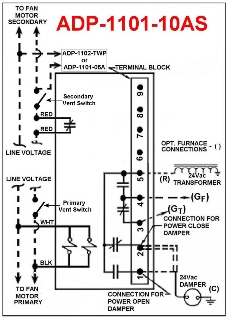
SHCEMATIC WIRING DIAGRAM
Adaptor 1101-10AS
Relay Coils: 120Vac; Points 24 Vac & 120 Vac-10A.
Note: This marking is also on label to be affixed adjacent to appliance wiring diagram. Additional wire shall be of the same size as originally used when completing electric circuits
For more information, please contact HMI HOYME Manufacturing Inc. @ 1-800-661-7382
Installation instructions – Printer friendly (pdf)
ADP-1101-10AS – Information Page