
HOM Combustion Air Damper Installation Instructions – Printer Friendly(pdf)
Installation Instructions for HMI Hoyme Motorized Combustion Air Control Control Damper – Vertical Mount – 24 Vac:
- Series HOM Interlocks With Safety Control Systems – Gas, Oil, Boilers & Furnaces
- This Installation shall be subject to the Approval of the Enforcing Authorities
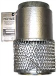
This Motorized Combustion Air Control Damper, Series HOM, fastens to the terminating end of a Fresh Air Inlet Duct leading into the heating appliance area and is designed to stop the inflow of cold air when not required. It is interlocked to the appliance safety control system and is designed to provide fresh air only during the firing cycle.
This Damper opens by gravity before the appliance fires and closes to save energy when the fire stops. The Appliance Transformer and/or an Auxiliary Transformer closes the Damper only after the fire stops thus preventing overloading the Appliance Transformer at any time. Diameters range from 4″ to 9 ” with the – (SF1) connected to one appliance and the – (SF2) connected to two appliances. To provide extra fresh air for the home during the firing cycle, this Damper may also be connected to a Ventilation/Replacement Fresh Air Damper, (series HAC) to simultaneously open with the HOM.
For voltages other than 24Vac, Interlocking Relay Adaptors have been designed to inter-lock to 250mVdc – 100Vdc and 120Vac Safety Control Circuits. Where the demand for combustion air exceeds the area of one Damper, i.e. commercial installations, several HOM Dampers may be connected together and mounted in MODULES to provide the necessary air for combustion.
Each Damper comes with an override manual ‘TEST/RUN SWITCH’. This switch is to be in the ‘UP’(run) position for normal operation of the damper. For details on the use of the Test/Run switch, see ‘Troubleshooting Procedure’.
Air Intake Duct Installation shall be in accordance with: In Canada – CAN/CSA B149 & B139; In the USA – ANSI/NFPA 54, 2006, ANSI Z223.1 and/or local codes including local codes relating to Ventilation Air Duct Installation.
A qualified contractor shall be consulted regarding air supply requirements for other appliances and for the building at large and regarding sealing of the building envelope. Notwithstanding the presence of this Damper, provision shall also be made for air supply to the appliance area as per codes cited above. If sizing codes are not available in certain locals, use: 1.0 sq. in. of duct cross-section per 7000 BTUH of total input rating of all appliances in that area.
The DAMPER is designed to be tight sealing, self cleaning with Nylon Bearings to provide many years of trouble free service. Lubrication is not necessary. Damper and appliance shall be inspected and serviced annually. If Damper fails to close when required, check for ‘UP’ position of the Test/Run switch. Do not obstruct the air intake duct. Have the Damper serviced immediately by qualified service personnel. Type SF2 shall be installed on or nearest the largest appliance and in the proximity of the secondary appliance.
ELECTRICAL WIRING shall be done in accordance with the National Electrical Codes or with Local Codes where they prevail. Additional wire shall be of the same size and type as used with existing Control Circuits. Wiring thereto shall be well secured and reasonably remote from any source of heat.
INSTALLER must be a trained, qualified person. Name and address of installer and date of installation shall be recorded on label located on central body. Labels and damper position shall be readily visible when in the installed position.
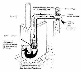
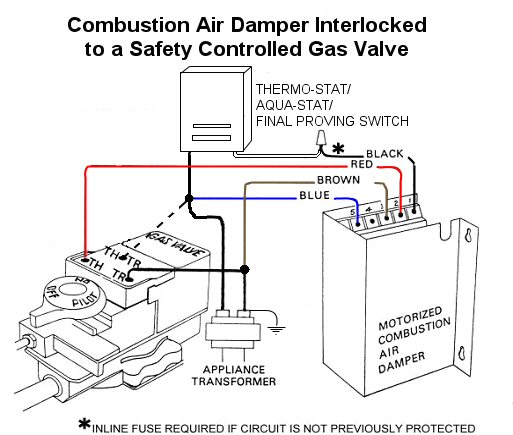
- HOM – Typical Installation for Gas Burning Appliance
- Before interconnecting this Damper to a safety control circuit, the heating appliance must be checked for proper operation, according it its manufacturer’s specifications and according to applicable codes.
- When connecting to other than 24Vac, use HOYME Relay Adaptors ADP-0MV2-S5A for DC circuits 50Vdc – 100Vdc and ADP-1102-S5A for 120Vac safety control systems.
- If needed, an approved 24Vac Transformer of ample capacity shall be added with the primary leads connected to the line voltage supply of the appliance
- If existing safety circuit is not fused, (as in older model furnaces) install an in-line fuse between the Thermostat Wire and the Damper black wire #1
- Always conduct a thorough check-out after installation is complete
- Sequence the appliance through at least three normal cycles to confirm proper operation
- Affix appropriate labels and follow instructions and warnings on each label
Mounting Procedure: See Diagrams Below:
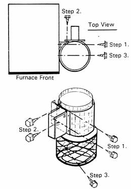
- Remove Mounting Bracket from Damper and screw to the side of the Appliance or Plenum making sure that no damage is done to any functional component of the appliance.
- Mount the bracket in the vertical position and align the bottom of the bracket within one foot above the burner level of the appliance and within two feet horizontally from the front
- It is recommended, but not necessary, to mount the damper so that air will discharge towards the front of the appliance
- With a Sheet Metal Screw, secure the bottom of the expanded metal cage to the side of the Appliance or Plenum. See Diagram, Step 3
Installation Package to include:
- 1 – Reverse Mounting Bracket
- 5 – #8 x 9/16” Sheet Metal Screws
- 1 – Wire Nut (Marrette) (2 for SF2)
- 3 – Labels, self sticking (6 for SF2)
- 1 – Installation Instructions
Schematic Wiring Diagram of Damper Series HOM Interconnected to 24Vac Safety Control System using the Appliance Transformer:
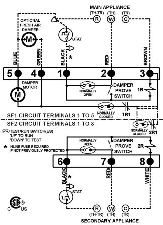
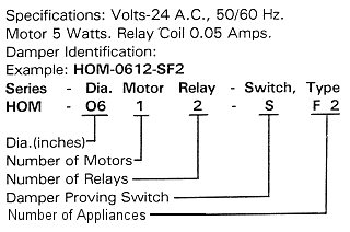
- Motor 5 Watts. Relay coil 0.05 Amps – Adjustment to thermostat heat anticipator is usually not necessary
- Note: This marking is also on label to be affixed adjacent to appliance Wiring Diagram
- Inline fuse required if circuit is not previously protected
- Fuse shall be rated at not more that 200% of the current drawn by the circuit
- Regular circuits __
- Damper Field circuits – – – – – – – – – –
- Internal connection, factory installed for Type SF2– – – – – –
- Jumper connection, factory removed for Type SF2 ===
- Additional wire shall be of the same size and type as originally used.
- Optional series ‘HAC’ Power Close Fresh Air Damper may be connected to damper terminals #4(Green) and #5(Blue)
- Check capacity of Transformer – 10W required only while appliance is not firing. – Damper drops open by gravity.
- Terminals #4 and #5 may be used only in accordance with the requirements of the Authorities having jurisdiction
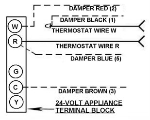
Hook-Up Procedure to a Regular 24Vac Heating Appliance:
Note: The TEST/RUN Switch on the side of the control body shall be in the ‘UP’ position for normal operation.
Note: Damper is Power Closed when appliance is not firing, and drops open by gravity when appliance fires or when the TEST/RUN switch is in the ‘DOWN’ position.
- Turn stat to lowest setting
- Turn off electrical power supply
- Connect Damper wire #5 (Blue), with a stat wire, to ‘R’ on appliance terminal strip. (‘TH-TR’ on Gas Valve 24Vac Live)
- Connect Damper #3 BROWN to ‘C’ on appliance terminal strip (‘TR’ on Gas Valve)
- Test by turning on power supply. Damper will close turn off power supply
- From ‘W’ on appliance terminal strip, (‘TH’ on Gas Valve) remove stat wire and with wire nut, connect to Damper #1 BLACK wire (Sensor).* Here is where In-line fuse is to be connected if circuit is not previously protected – applies to older type appliances
- Connect Damper #2 RED wire to ‘W’ on appliance terminal strip (‘TH’ on Gas Valve)
- Turn stat to call for heat. Damper will open and appliance will operate normally
When using Type SF2, Damper terminals 6, 7 and 8 (Wires: Blk, Red & White) are to be connected to second appliance respectively and in similar manner as terminals 1, 2 and 3 above.
When checking for proper operation of the SF2 damper, turn power on to both appliances so that the damper will operate from either thermostat.
N.B. DO NOT GROUND GREEN WIRE. Green wire is only used when connecting to an HAC damper.
— — — — — Damper Wires Field Installed
Schematic Wiring diagram of Damper Series HOM Interconnected to 24Vac Safety Control System Using an Auxiliary Transformer:
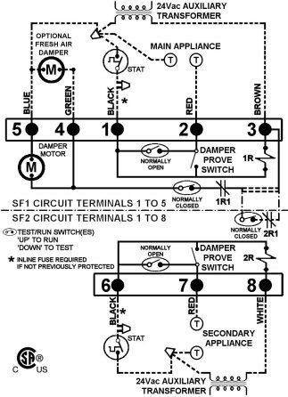
- Motor: 5 Watts. Relay Coil: 0.05 Amps.- Adjustment of thermostat heat anticipator is usually not necessary
- HOM – Auxiliary Transformer
- Note: This marking is also on label to be affixed adjacent appliance wiring diagram
- * Inline fuse required if circuit is not previously protected
- Fuses shall be rated at not more than 200% of the current drawn by the circuit
- Regular circuits : ________
- Damper Field circuits: – – – – – – – – – –
- Internal connection, factory installed for Type SF2: – – – – – –
- Jumper connection, factory removed for Type SF2: = = =
- Additional wire shall be of the same size and type as originally used
- Optional series ‘HAC’ Power Close Fresh Air Damper may be connected to HOM terminals 4(Green.) and 5(Blue)
- Check capacity of transformer. (10W required only while appliance is not firing. – Damper drops open by gravity)
- Terminals #4 and #5 may be used only in Accordance with the Requirements of the Authorities having jurisdiction
- Installation of the auxiliary 24Vac Transformer leads must be connected to the line voltage of the appliance
- Follow applicable codes
Hook-Up Procedure Using Auxiliary Transformer – 24Vac:
Note: This installation may be used where Appliance Transformer Circuit is not known or Appliance Transformer turns off after the firing cycle. The Auxiliary Transformer keeps the Damper closed during the non firing of the appliance. This installation is especially suitable for OIL Safety Control Systems.
Note: TEST/RUN Switch on the side of the control body shall be in the ‘UP’ position for normal operation.
NB: For PROPER PHASING of AUXILIARY Transformer, Refer to Instruction #9.
- Turn stat to lowest setting
- Turn off electrical power supply and install auxiliary transformer
- Remove a stat wire from an appliance stat terminal and by using a wire nut, join four wires: Stat wire, Damper #5 BLUE wire, 24Vac auxiliary wire and a stub wire. Connect stub wire back to appliance stat terminal
- Connect Damper #3 BROWN wire to the remaining 24Vac auxiliary transformer wire.
- Test by turning on power supply. Damper will close. Turn off power supply
- From the remaining appliance stat terminal, remove this stat wire and connect to Damper #1 BLACK wire with wire nut supplied. (Sensor). NOTE: * In-line fuse to be connected here if circuit is not previously protected
- Connect Damper #2 RED wire back to appliance stat terminal. (Signal)
- Turn on power supply and Damper should close. If Damper does not close, interchange auxiliary transformer wires, turn on power and Damper will close
- Check for PROPER PHASE of AUXILIARY TRANSFORMER by momentarily jumping Damper #1 BLACK wire to Damper #2 RED wire. If Damper opens, an out-of-phase trans-former is indicated. Correct by inter-changing auxiliary 24Vac Transformer Wires and retest
- Turn stat to call for heat. Damper will open and heating appliance will operate normally
When using Type SF2, Damper terminals #6(Blk), #7(Red) and #8(WhItE) are to be connected to second appliance respectively and in similar manner as Damper terminals #1(Blk), #2(Red) and #3(Br) above. When checking for proper operation of the SF2 Damper, turn power on to both appliances so that the Damper will operate from either Thermostat.
N.B. DO NOT GROUND GREEN WIRE . Green wire is only used when connecting to an HAC Damper.
Troubleshooting ‘HOM’ Combustion Air Control Dampers Having Test/Run Switches:
General: The Damper uses power to close when the appliance is not firing and does not use power when the appliance is firing. This prevents overloading the Transformer during the firing cycle.
Two wires from the motor are connected to the Appliance Transformer and two wires from the Damper End Switch are connected in series with one stat wire.
Condition: Damper does not close after appliance completes its firing cycle.
Cause:
- Test/Run Switch is not in the ‘Up’ position or
- A Faulty Relay or
- No power supply or
- A faulty Motor
Procedure:
- Check Test/Run Switch to be in the ‘Up’ position. If no response
- Remove control body cover and use a jumper between Terminals 3 & 4. If Damper closes – faulty relay. If no response
- Check power supply to terminals 3 & 5 or
- Connect power supply to Terminals 4 & 5. No response indicates a faulty Motor
Condition: Damper does not open when stat asks for heat.
Cause:
- Signal is not getting through from the stat to the Relay or
- Damper is stuck closed or
- Mechanical friction in Motor Gears
Procedure:
- Check In-line Fuse, if used, between stat wire and Damper black wire #1. If this is not the cause, remove control body cover and with jumper, join terminals 1 & 5. If Damper opens, a faulty stat is suspected. Turn Test/Run Switch to the ‘Down’ position and if appliance does not fire, a faulty stat is confirmed
- If the Damper has not been activated for a period of time, (e.g. summer months) the Damper might stick closed due to residue. Clean the Damper blade with soap and water
- Motor Gears wear with age causing increased friction which prevents the Damper from opening freely. Replace motor
Condition: Damper opens on stat signal but appliance does not fire.
Cause:
- Appliance faulty or
- Improper linkage to the End Switch or
- A faulty end switch.
Procedure:
- The Combustion Air Damper is interlocked with the heating appliance control system. This feature is by-passed by using the TEST/RUN Switch in the down position. This re-connects the stat wire direct to ‘W’ (TH) on the appliance. If heating appliance does not fire with this switch in the down position, a faulty heating system is suspected. If appliance responds,
- Check end switch linkage by listening for a ‘click’ as the Damper Blade opens to approximately 30 degrees. To correct, bend Switch Lever Arm to suit.
- If End Switch clicks and appliance does not respond, a faulty End Switch is suspected.
DAMPER CONTROL with TEST/RUN Switch:
This feature makes it possible to control the Damper in the open position should extra ventilation be desired for a longer period of time. The Damper, however, shall open and remain open while the TEST/RUN Switch is in the down position.
* IN-LINE FUSE HOLDER AND FUSE:
Part number #3152-001 includes 3 amp Fuse. Not supplied with Damper. May be ordered direct from the factory.
For more information, please contact HMI HOYME Manufacturing Inc. @ 1-800-661-7382, or www.hoyme.com
HOM Combustion Air Damper Installation Instructions – Printer Friendly(pdf)