
Two Forced Air Furnaces sharing a Replacement Air Supply Duct controlled by one Fresh Air Damper with Power Open Damper:
#8C5. Two Forced Air Furnaces Sharing a Replacement Air Duct with a Power Open Fresh Air Damper (HAC-0x10-OPO) with One Adaptor (ADP-1102-TWP) Interconnecting a designated Ventilation Switch with One Furnace and a second Adaptor (ADP-0241-05A) controlling the second Furnace.
HMI Hoyme Manufacturing Inc. Special Note: Circuits are colored for clarification only and are not necessarily those found in actual installations. Combustion Air Damper Wires, however, are colored as shown.
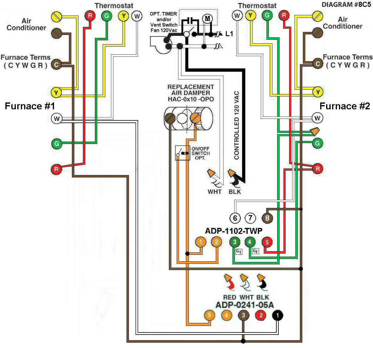
Diagram #8C5: Two Forced Air Furnaces sharing a common Replacement Air Supply Duct equipped with one Power Open Fresh Air Damper. A designated Ventilation Switch and/or Bathroom Timer interconnected to an ADP-1102-TWP acting as a control centre for one Furnace and an ADP-0241-05A interconnected and acting as a control centre for the other Furnace.
- Replacement Air Control Damper, Power Open (HAC-0x10-OPO) where ‘x’ = diameter of the Damper. (Note: If using a Power Close Damper, go to wiring Diagram #8C6 for details.)
- Ventilation switch and/or Bathroom Timer
- 24Vac Relay Adaptors (ADP-1102-TWP) and (ADP-0241-05A)
OPERATION:
- Damper opens when either Furnace fires
- The ventilation switch simultaneously turns on the Exhaust Fan, opens the Damper and turns on the Circulation Fan on one Furnace only
- Optional Switch allows full control of Replacement Air Damper to open as required
N.B. Replacement Air Damper is not affected by the ‘Manual’ setting of the Furnace Fan or by the operation of an Air Conditioner.