
Installation instructions – Printer friendly (pdf)
RADP-1102-TPX – Information Page
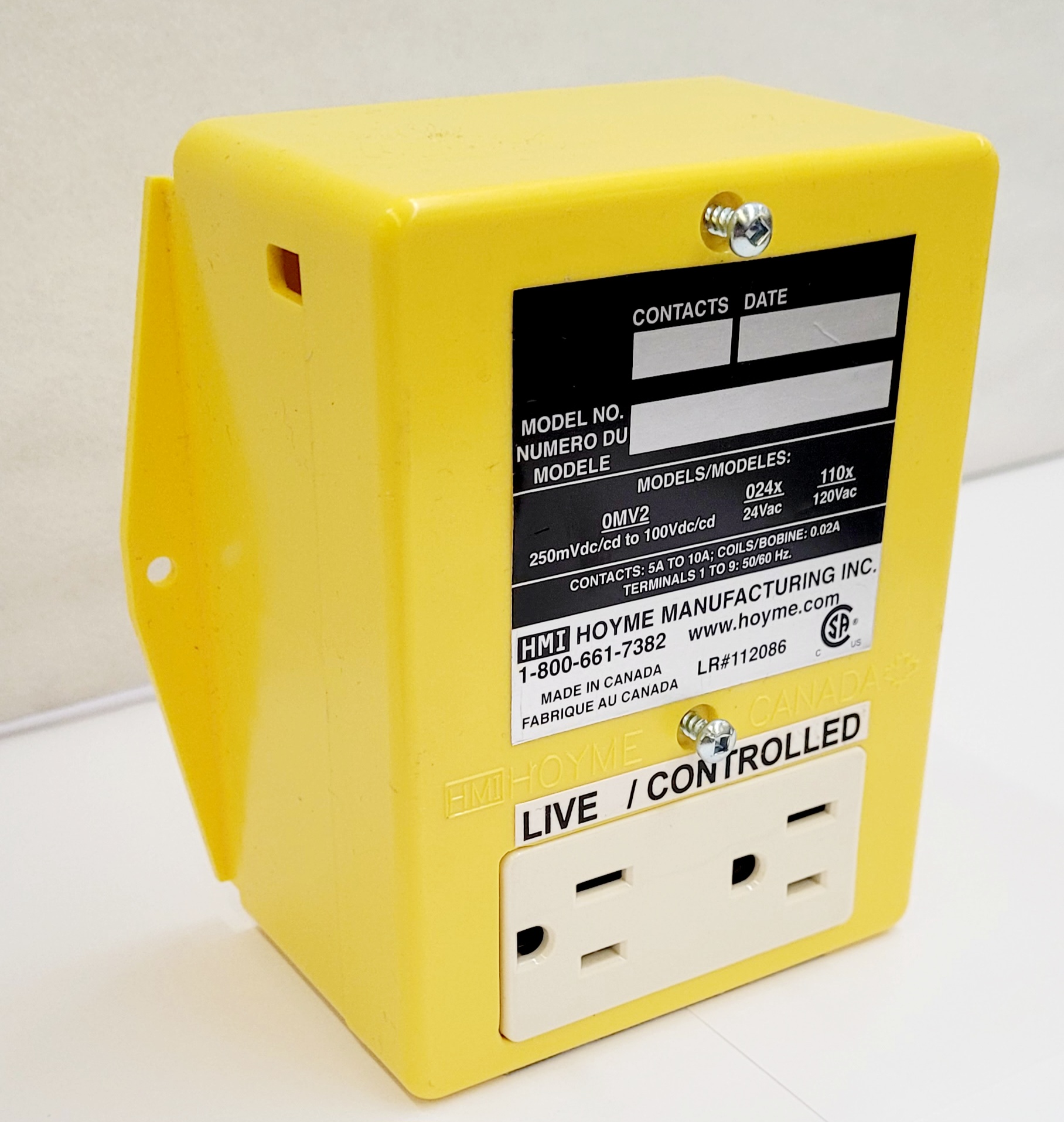
Installation Instructions for HMI HOYME RADP-1102-TPX
A Dual Voltage Control Center that INTERLOCKS a 24 Vac Motorized Air Inlet Damper with End Switch to a 120 Vac Plug-in Exhaust Fan and Furnace Circulation Fan
- 4” x 5” x 2 ½” – 101 x 127 x 64 mm
- Installation Of This Adaptor Shall Be In Accordance With The Requirements Of the Authorities Having Jurisdiction
- Fitness of this Adaptor/Damper combination to satisfy air supply requirements for fuel fired appliances during operation of the interconnected exhaust fan(s) shall be investigated by the enforcing authorities

This Adaptor (RADP-1102-TPX), by using a Manual Switch or Timer, acts as an automatic control centre to:
- Open a 24Vac Motorized Air Inlet Damper with End Switch (interlocked) which proves to be open
- Before the plug-in Exhaust Fan turns on and
- Simultaneously turns on a Furnace Circulation Fan
It has two Relays and a split Duplex Receptacle; one side live and the other side controlled. If using a Damper without an End Switch, a jumper wire is required between Adaptor terminals #1 and #4. As a result, the fans and the damper will not be interlocked but will operate simultaneously
Air Intake Duct installation shall be in accordance with: In Canada – CAN/CSA B149 & B139; In the USA – ANSI/NFPA 54, 2006, ANSI Z223.1 and/or local codes including local codes relating to ventilation air duct installation.
I.D: RADP -1102 –TPX comes with 2 relays:
1 Relay DPDT: Coil .02A, 120Vac. Pts 24Vac- 5A
1 Relay SPDT: Coil. 02A, 24Vac. Pts 120Vac, 10A
1- Split Duplex Receptacle, LIVE/CONTROLED
- Adaptor line voltage leads are connected only to the live side of the Receptacle
- Line voltage leads shall be suitably cabled, fastened and enclosed in suitable raceways
- Refer to local and applicable codes
- Always conduct a thorough checkout after installation is complete
- Affix appropriate labels and follow instructions and warnings on each label
Instructions
The following hook-up procedures are suggestions only and do not limit the uses of this Adaptor
How to install a Damper with End Switch: Damper proves to be Open before starting the Plug-In Exhaust Fan and turning on a Furnace Circulation Fan
- Turn thermostat to lowest setting
- Turn off electrical power to furnace
- Turn off electrical power leading to Adaptor
- Select suitable location for the Adaptor
- Select a suitable location for Inlet Damper. Connect Damper #3 to Adaptor#3 and connect Damper #5 to Adaptor #1 for Power Open Damper or Adaptor #2 for Power Close Damper
- Check capacity of 24Vac transformer
- To interlock Damper so that it opens before Exhaust Fan starts, connect Damper #4 to Adaptor #1 and Damper #2 to Adaptor #4
- Connect Adaptor terminal #5 to furnace R, Adaptor terminal #3 to furnace C (or ground) and Adaptor terminal #6(GF) to furnace G. If thermostat wire is presently connected to furnace ‘G’, remove it from ‘G’ and connect it to Adaptor terminal #7(GT).
- Connect LINE voltage wires to the Receptacle, LIVE HALF only, as per wiring diagram
- Connect the two wires of the manual ventilation switch (or timer) to the Adaptor with one wire going to the line voltage terminal on the Receptacle. Connect the other wire of the manual switch (or timer) to the Adaptor Black wire with a wire nut
- Turn on 120Vac power supply to the Adaptor and 120Vac power supply to furnace.
- Turn on the ventilation switch (or timer) and the damper with end switch, being interlocked, will Open to cause the Exhaust Fan and Furnace Circulation Fan (if not running) to now operate. Note: If jumper wire is used instead of damper end switch, all appliances will then operate simultaneously.
- Turn thermostat to normal setting and furnace will fire normally. If Instruction No. #5 with Option 1) or 2) is followed, then the Fresh Air Inlet Damper will also open during furnace firing.
If Inlet Damper is also required to open during furnace firing:
- Use PC Damper with end switch and relay and follow its instructions, or if Combustion Air Damper is connected to the furnace, connect terminal #3 of the PC Damper (minus the relay) to Combustion Air Damper terminal #4
Schematic Wiring Diagram of ADP-1102-TPX with Duplex Receptacle Connected to Furnace Circulation Fan Plug-in Ventilation Fan and Motorized Fresh Air Inlet Damper with End Switch (or Jumper)
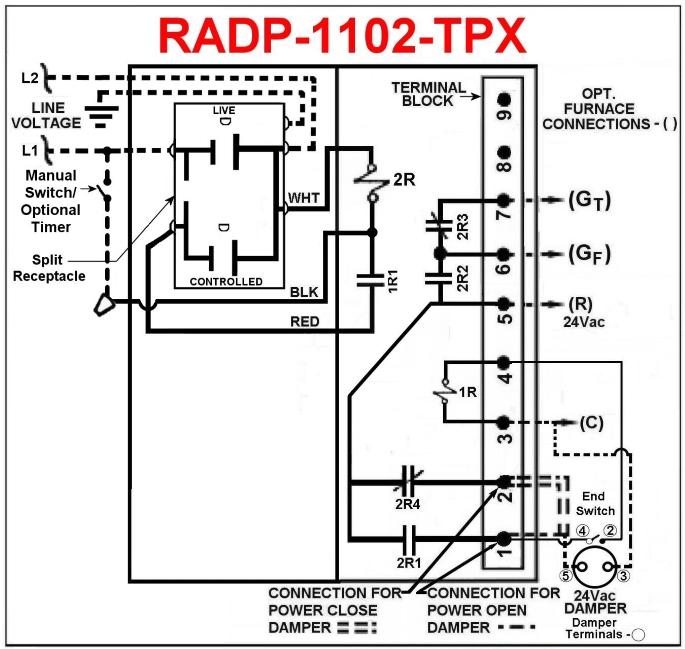
– – – – – – – – – – Field Wiring
Note: this marking is also on label to be affixed adjacent to appliance wiring diagram.
Additional wire shall be of the same size as originally used when completing electric circuits
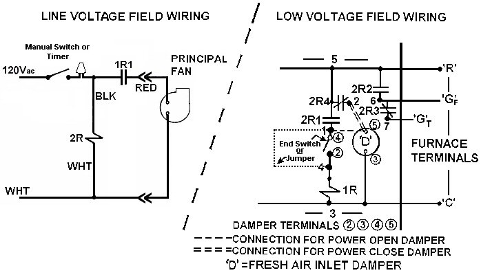
Ladder Type Diagram
For More Information, please contact HMI Hoyme Manufacturing Inc. PH. 1-800-661-7382
Installation instructions – Printer friendly (pdf)
RADP-1102-TPX – Information Page