
Vent Switch, Replacement Air – Power Open, interconnected with Exhaust Fan heating cycle and/or cooling cycle-without A/C:
#6C2. Ventilation Switch, Two Adaptors (ADP-1102-TWP) and (ADP-0241-05A), One Power Open Replacement Air Damper (-PO) interconnected with Exhaust Fan, Heating and/or Cooling, Damper Opens with or without A/C but not interconnected with A/C.
HMI Hoyme Manufacturing Inc. Special Note: Circuits are colored for clarification only and are not necessarily those found in actual installations. Combustion Air Damper Wires, however, are colored as shown.
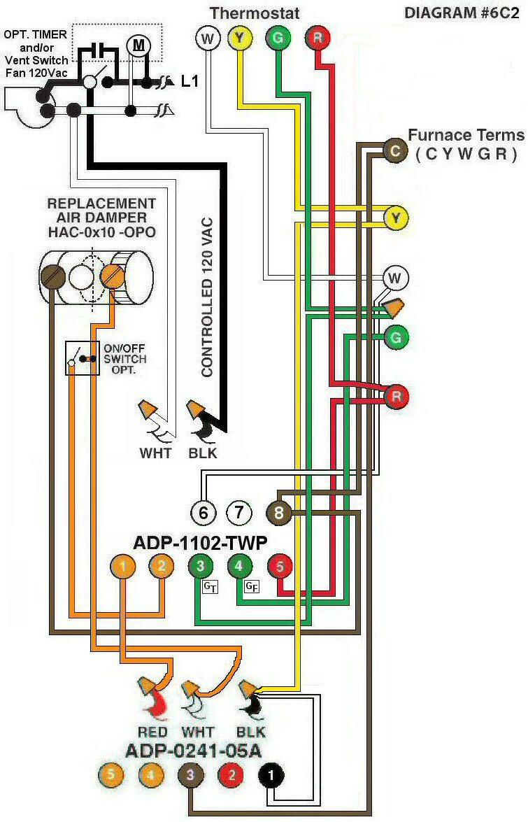
Diagram #6C2: Forced Air Furnace having a Replacement Air Supply Duct together with an Exhaust Fan controlled by a designated Ventilation Switch and/or Bathroom Timer. Air Conditioner is not part of this system.
- Use Replacement Air Control Damper (Power Open) – (HAC-0x10-OPO)
- Ventilation Switch and/or Bathroom Timer to supply controlled 120Vac to Furnace area
- Relay Adaptor (ADP-1102-TWP) to function as a control center
- Relay Adaptor (ADP-0241-05A) to function as a fresh air supply when Thermostat is set to the cooling cycle
OPERATION:
- Replacement Damper opens to provide fresh air during the heating and/or cooling cycle.
- Ventilation Switch and/or bathroom timer turns on Ventilation Fan, opens Replacement Air Damper and turns on Furnace Fan simultaneously
- For the cooling cycle, (use when outside temperature cool) thermostat will simultaneously turn on the Furnace Fan and open the Replacement Air Damper
- Damper will remain closed during manual Furnace Fan operation
- On/Off Switch connected to (ADP-1102-TWP) Terminal #2 (as shown) allows manual control of the Replacement Air Damper to open as required
If installing an Air Conditioner at a later date, disconnect (ADP-0241-05A) from “Y” to leave Damper closed during A/C operation. For systems with existing A/C use Diagram #6C1 (to keep Damper closed during the A/C operation) or refer to Diagram #6C3 to open Damper during A/C operation.