
120Vac Vent Switch, Combustion Air(2 furnaces), Replacement Air:
#5B1. Two Furnaces, Combustion Air Damper (-SF2), Two Power Close Fresh Air Dampers (-PC) c/w Relays operating separately with One to Each Furnace, also Open when Furnaces Fire. Included is an Exhaust Fan and a 120vac Adaptor (ADP-1101-05A) to Open the Main Fresh Air Damper and start the Furnace Fan.
HMI Hoyme Manufacturing Inc. Special Note: Circuits are colored for clarification only and are not necessarily those found in actual installations. Combustion Air Damper Wires, however, are colored as shown.
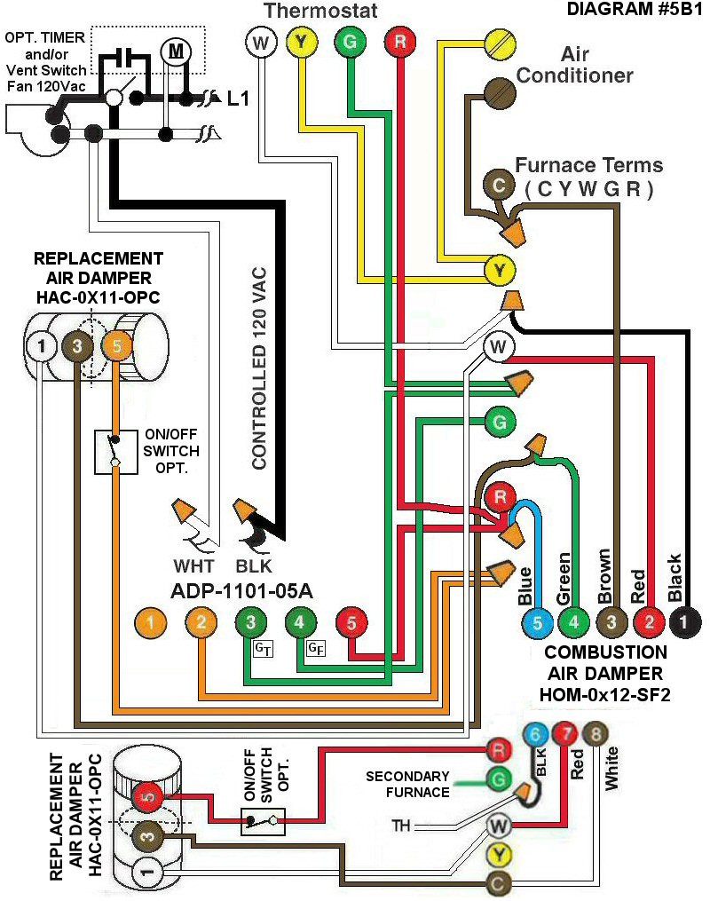
Diagram #5B1: Two Furnaces having a Common Combustion Air and two Replacement Air Supply Ducts together with an Exhaust Fan controlled by a designated Ventilation Switch or Bathroom Timer.
- Combustion Air Damper for two Furnaces (HOM-0x12-SF2)
- One HAC-0x11-OPC Damper with Relay used with Adaptor ADP-1101-05A connected to the primary Furnace only
- One HAC-0x11-OPC Damper with Relay connected to the secondary Furnace
OPERATION:
- The Combustion Air Damper opens when either Furnace fires
- Primary Replacement Air Damper HAC-0x11-OPC opens when primary Furnace fires and also opens when Ventilation Fan is on
- Ventilation Switch and/or timer turns on the Exhaust Fan, the primary Furnace Fan and opens the primary HAC Damper simultaneously
- The secondary Damper HAC-0x11-OPC opens only when the secondary Furnace fires or when an overriding optional switch is used
- Optional Switch (i.e. toggle switch, timer, de-humidistat) on each HAC Damper allows independent control of each Damper
N.B. Replacement Air Dampers are not affected by the ‘Manual’ setting of the Furnace Fan.