
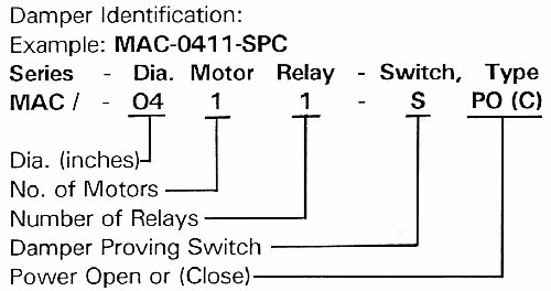
MAC Make-Up Air Terminating Damper Installation Instructions – Printer Friendly(PDF)
Installation Instructions for HMI Hoyme Motorized Replacement (Make-Up) / Ventilation Air Control Damper – 24Vac – for Terminating End of Duct:
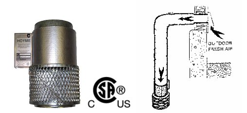
Replacement/Ventilation Air Damper Controls the Fresh Air Inlet. It may be interconnected to Kitchen Fans, Exhaust Fans Fireplaces and Heat Recovery Ventilators. Go to series ‘HOM’ for combustion air supply.
This installation shall be subject to the approval of the enforcing authority. Air supply and air duct installation shall be in accordance with the National Building Codes and/or local codes.
- Refer also to HOYME Installation Instructions: Combustion Air Control Damper, Series HOM; Adaptor 0241-10A (24Vac – switches line voltage); and Adaptor 1101 (line voltage – switches 24Vac)
- Specs.:24Vac, 50/60 Hz. Motor 5 watts. Relay Coil 0.05 Amps. A separate Transformer 24Vac of sufficient capacity is required for most installations
AIR CONTROL DAMPERS are designed to be tight sealing, self cleaning with nylon bearings to provide many years of trouble free service. Damper and Appliance shall be checked annually
ELECTRICAL WIRING shall be done in accordance with the National Electrical Codes or with Local Codes where they prevail. Additional wire shall be of the same size and type as used with existing control circuits
INSTALLER must be a trained, qualified person. Name and address of installer and date of installation must be recorded on label located on central body
MAC Series shall be fastened with screws to the terminating end of an adequately supported air duct.
Wiring Diagrams shown are suggestions only and do not limit other ways of wiring.
General Instructions:
- Install Air Control Damper as per mounting instructions above
- Turn off electrical power supply and connect electrical wires as per diagram appropriate to the Damper being installed. Follow applicable codes
- Connect 24Vac, 50/60 Hz. Transformer of sufficient capacity to 120Vac fan circuit or power circuit as per appropriate wiring diagram below
- Connect 24Vac Circuit using ample length of wire to reach each Damper
- Re-check and confirm that choice of Damper matches proper Wiring Diagram
- Turn on electrical power supply. Dampers in the open position will now close
- Turn on appliance (or switch) and where necessary, cause re-circulating fan to operate. Air control Damper(s) will open as per Wiring Diagram
- Affix appropriate labels and follow instructions and warnings on each label
Selected Schematic Wiring Diagrams Typical for MAC Dampers:
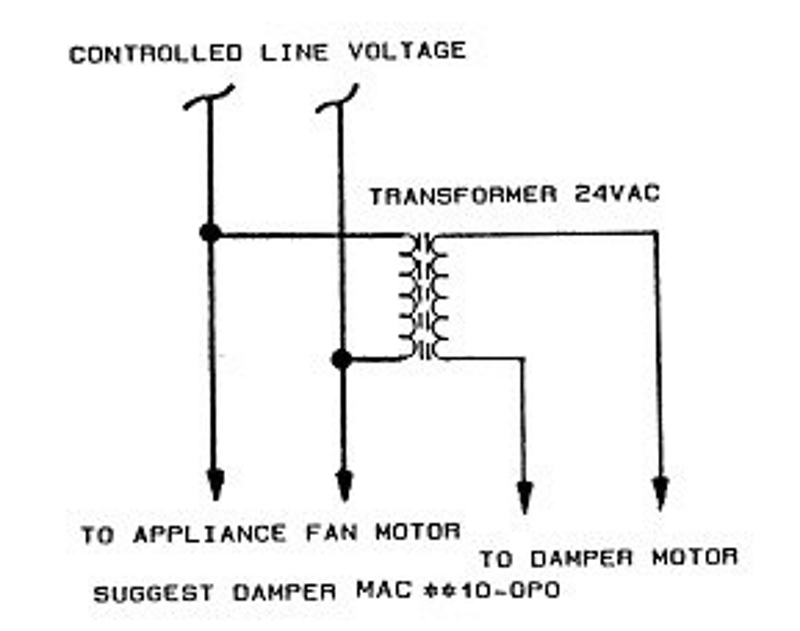 | A. – Connected to a controlled 24Vac Transformer. Suggestion: MAC-XX10-OPO Note: This marking is also on label to be affixed adjacent to appliance wiring diagram. |
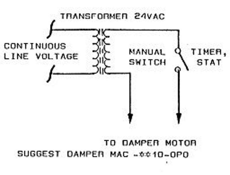 | B. – Controlled by an automatic timer, stat or manual switch. Suggestion: MAC- XX10-OPO |
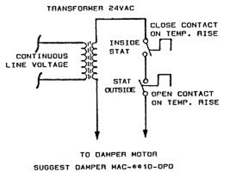 | C. – Controlled by inside and outside thermo stats.Suggestion: MAC-XX10-OPO |
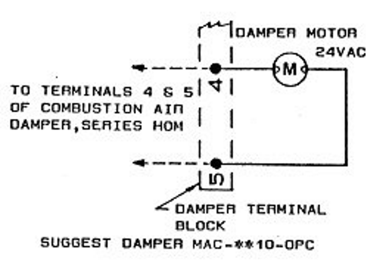 | D. – Controlled by Combustion Air Damper, Series HOM. Suggestion: MAC-XX10-OPC |
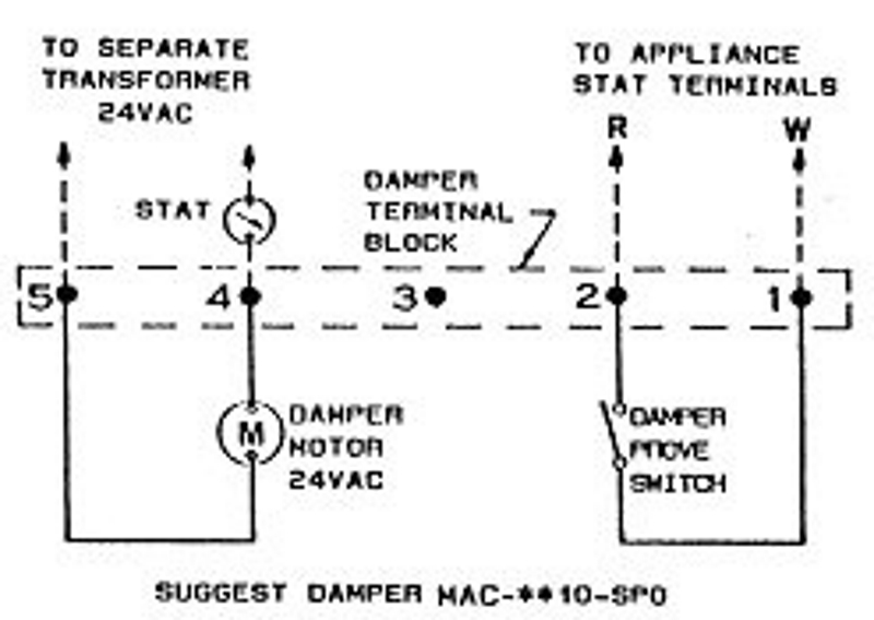 | E. – Controlled by a Thermostat in series with a separate 24Vac Transformer Damper proving switch replaces the thermostat and is connected to the Thermostat Terminals of the heating appliance Suggestion: MAC-XX10-SPO |
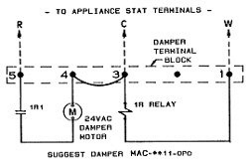 | F. – Controlled by appliance Thermostat with Damper wire(1) connected to appliance W Damper wire(3) connected to C (Ground) and Damper wire(5) connected to R on appliance terminal strip Damper powers open when Thermostat calls for heat Suggestion: MAC-XX11-OPO Note: This marking is also on label to be affixed adjacent to appliance wiring diagram |
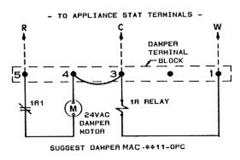 | G. – Controlled by appliance thermostat with Damper wire (1) connected to W, Damper wire (3) connected to C and Damper wire (5) connected to R on appliance terminal strip. Appliance transformer actuates Damper closed when appliance is not firing. Damper opens when thermostat calls for heat Suggestion: MAC-XX11-OPC Check tag on Damper cable for number and colour identification. Note: This marking is also on label to be affixed adjacent to appliance wiring diagram. |
 | H. – Wiring for MAC-0x11-SPC Damper |
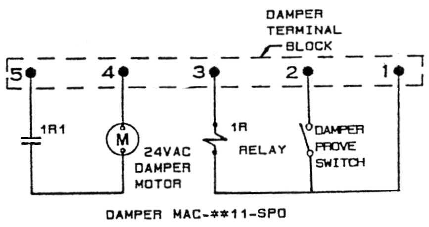 | I. – Wiring for MAC-0x11-SPO Damper |
For more information, please contact HMI HOYME Manufacturing Inc. @ 1-800-661-7382, or www.hoyme.com
MAC Make-Up Air Terminating Damper Installation Instructions – Printer Friendly(PDF)MAC Product Information Page