
24Vac Vent Switch, Combustion Air, and Replacement Air with Two Exhaust Fans and two individual Timers Power Close:
#7A1. Two 24vac Ventilation Switches/Timers and Two Exhaust Fans, Combustion Air Damper (HOM-0x11-SF1), One Adaptor (ADP-0241-10A) and 7 Pole Connector, One Power Close Replacement Air Damper (HAC-0x10-OPC). Also turns on Inlet Fan.
HMI Hoyme Manufacturing Inc. Special Note: Circuits are colored for clarification only and are not necessarily those found in actual installations. Combustion Air Damper Wires, however, are colored as shown.
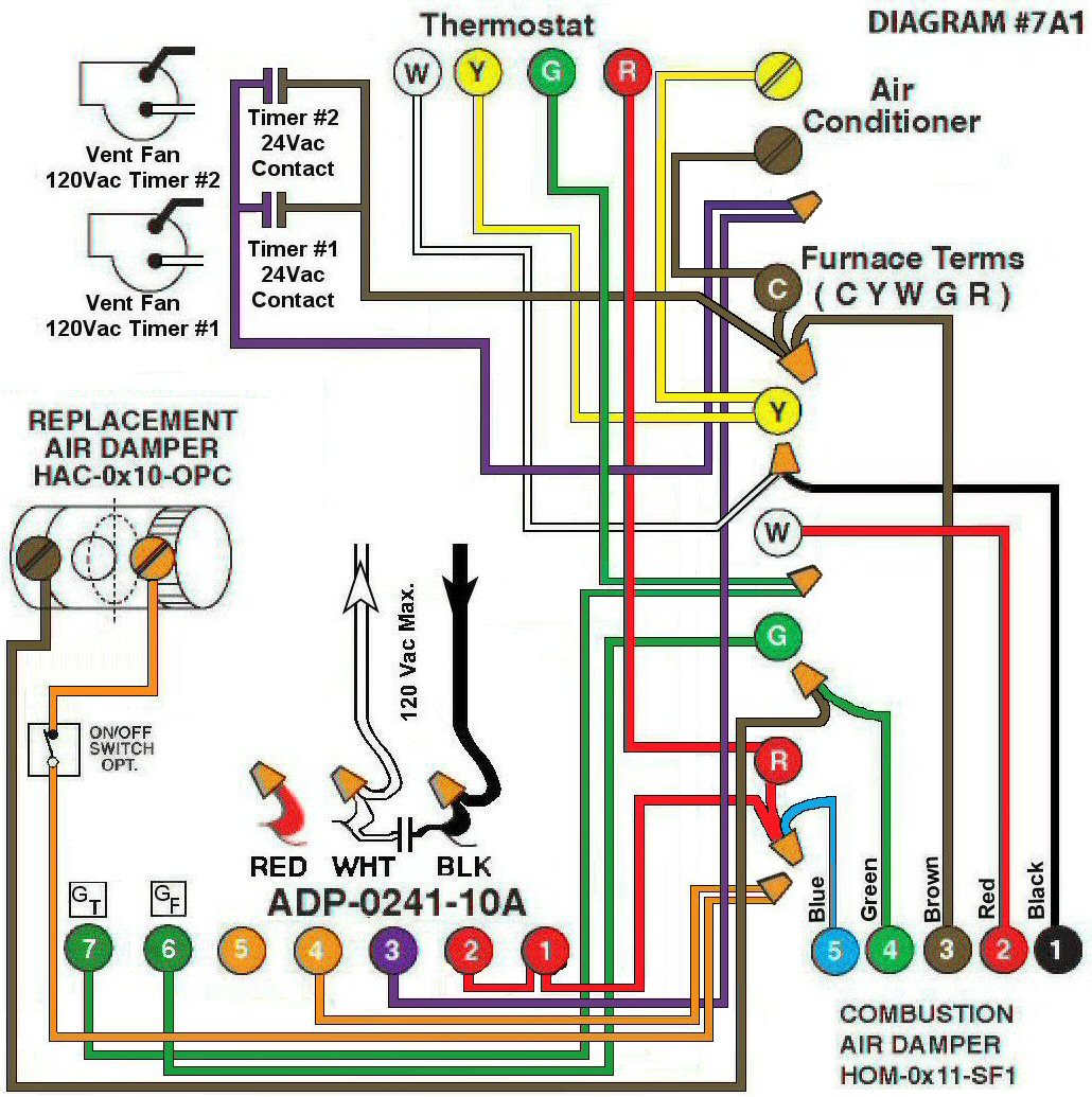
Diagram #7A1: A Forced Air Furnace, a Combustion Air Supply Duct, a Replacement Air Supply Duct, two Exhaust Fans, two individual Timers and an Adaptor ADP-0241-10A.
- Combustion Air Damper (HOM-0x11-SF1)
- Replacement Air Damper (HAC-0x10- OPC)
- Two exhaust fans having individual timers with 24Vac switching capabilities
- 24Vac Relay Adaptor (ADP-0241-10A) to function as a control center
OPERATION:
- Combustion Air Damper and Replacement Air Damper open during Furnace firing
- Ventilation Switch/Timer (either one) turns on Exhaust Fan(s), opens Replacement Air Damper and turns on Furnace Fan simultaneously
- Optional Switch (i.e. toggle switch, de-humidistat) allows full control of Replacement Air Damper to open as required provided it is a Power Close type
N.B. Replacement Air Damper is not affected by the ‘Manual’ setting of the Furnace Fan.