
Hoyme-EWS-installation-instructions.pdf
Emergency Water Shut-Off Product Page
Installation Instructions for Emergency Water Shut-Off – EWS
Stop Leaks Before They Turn Into Flood!
- The EWS is designed around a cube which sits on the floor and dissolves whenever it comes in contact with water, when this happens, the unit allows a weight to fall, thereby shutting off the valve.
- The EWS can be applied directly to hot water tanks or main water lines without electrics. the EWS can also be supplied with a 24Vac solenoid and Remote Sensors to control a leaking sink, dishwasher, toilet or washing machine.
- The basic kit c/w top quality 3/4″ shutoff ball valve, multi-hole valve bracket, trip weight, channel & Cable guide, 5 ft of 1/16″ cable, mounting crews & one Soluble cube.
- The 24 Vac Solenoid Type c/w the above plus 1 remote sensor & a 24 Vac Transformer (additional sensors are extra)
- Basic kit shipping weight – 8lbs (3.18Kg)
- Manufactured by: Hoyme Manufacturing Inc. Camrose, AB, Canada C
- PAT. Protected By JENS JENSEN
- 1-800-661-7382 (U.S. & CANADA)
Installation Instructions For Emergency Water Shut-off (EWS)
- Select location for the Emergency Water Shut-off valve. (EWS)
- Main water supply line;
- Domestic Hot Water (DHW) inlet supply line;
- Other location, a low spot should prove to be best;
- Main line for 24VAC solenoid type.
- Remove weight from channel guide and insert 1/4″ bolt and washer on face side of weight ready for cable fastening. (See Fig. 1).
EWS – Fig. 1
EWS- Fig. 2
EWS-Fig.3
- 3. If mounting EWS on DHW tank, select location to mount channel guide in relation to the floor and the selected position of the EWS valve. (See Fig. 2)
- If connecting to main supply line, position EWS valve after main shut-off valve.
- 4. Place channel guide in vertical position with bottom end resting on the floor. Best to use a level for vertical accuracy.
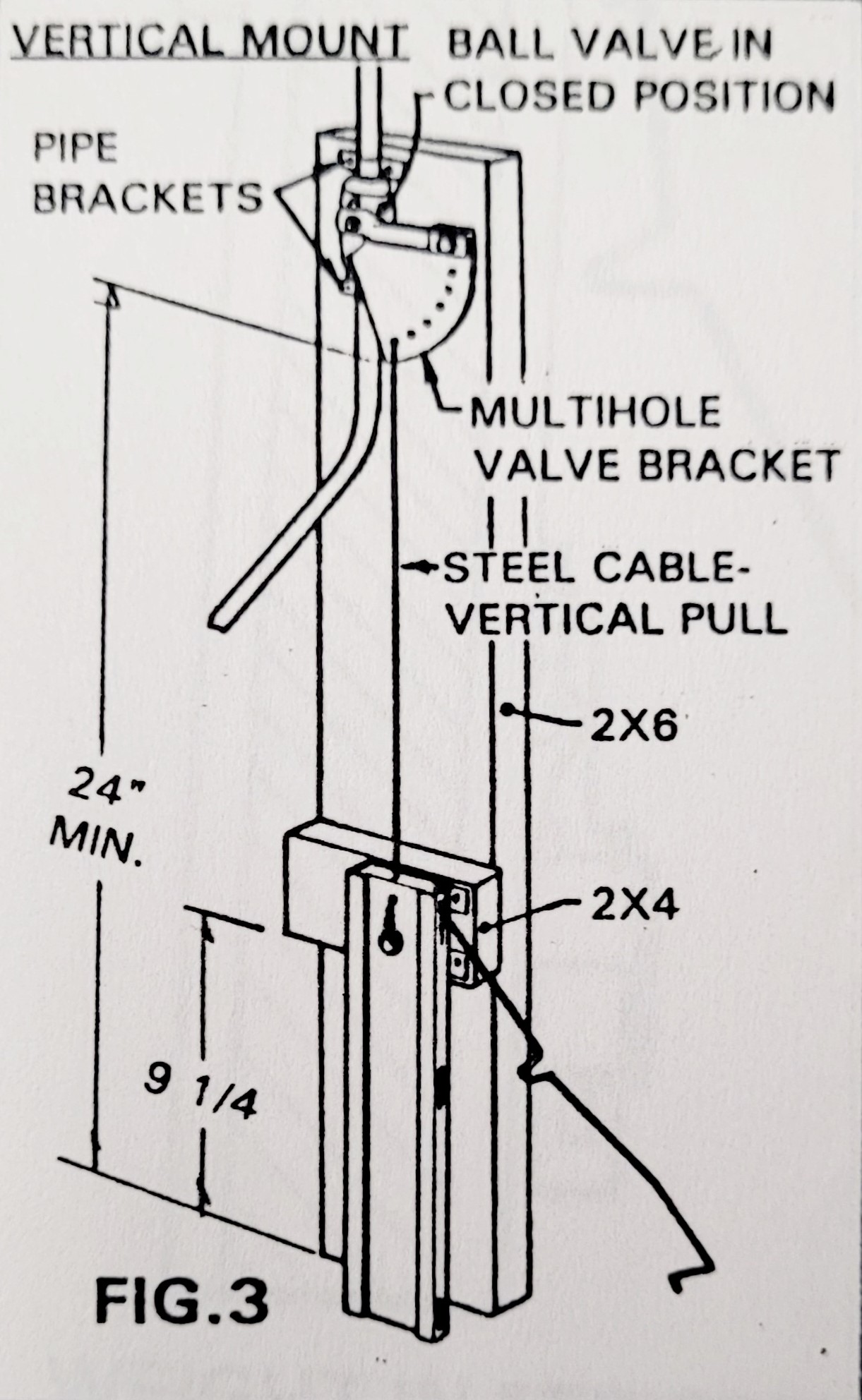
- 5. Drill 3/32″ holes for the four mounting screws. (See fig. 1 .) If drilling into the insulated jacket, be careful not to damage the hot water tank. For mounting EWS valve on main water supply line, use a 2×6 vertically to support the EWS valve body and a 2×4 horizontally to support the channel guide. (See Fig 3 & 4).
- 6. Fasten channel guide into place by using four sheet metal screws supplied.
- 7. Insert the weight into the channel guide so that both rest on the floor.
- 8 . Fasten cable guide bracket to top of DHW tank so that the cable under tension will be vertical to top centre hole of weight. (See Fig. 2), (top view) and (Fig. 5).
EWS – Fig. 4
EWS – Fig. 5
EWS – Fig. 6
- 9. Turn off water supply. For DHW, turn temperature control to lowest setting.
- For hot water tank mounting, allow at least 3″ clearance between EWS valve and top of water tank. (See Fig. 2).
- For main water line installation, allow at least 24″ clearance between lowest point of a closed EWS valve and floor. Support the EWS valve and assembly with a 2×6 extended vertically from the EWS valve to the floor. Fasten EWS valve with two 3/4″ pipe brackets. (See Fig. 3 & 4).
- 10. Cut water supply line and provide space for the EWS valve to be inserted. IMPORTANT: EWS valve is to be inserted so that the EWS valve handle is in the lowest position when valve is closed. Highest position when valve is open. Do not permanently secure EWS valve into place until instruction #13.
- 11. Mount multi-hole cable bracket to EWS valve handle with 1/4″ truss bolt and nut. Note position of multi-hole cable bracket on EWS valve handle for VERTICAL valve installation. Fig. 5. Note position of multi-hole cable bracket on EWS valve handle for HORIZONTAL valve installation. (Fig. 6).
- 12. With EWS valve in closed position, rotate valve body on water supply line so that the multi-hole bracket is in line with the cable guide bracket. (See Fig. 2, top view.) If guide bracket is not used, then rotate EWS valve body on supply line so that the multi-hole bracket is directly in line with the top centre hole of the weight. (See Fig. 3 & 4).
- 13. Secure valve body permanently into place. Check for water leaks by opening the water supply valve and the shut-off valve. After test, close shut-off valve.
- 14. Thread the 11/16″ cable through a proper hole in the multi-hole bracket so that proper dimensions can be achieved as shown in dimension A. (See Fig. 7).
EWS – Fig. 7
EWS – Fig. 8
- 15. Continue by threading cable through guide bracket (if used), down through top centre hole of weight, under washer of 1/4″ bolt and back through top centre hole of weight. Extended cable helps in adjustment required in #16.
- 16. Adjust cable tension so that weight will be suspended off the floor the thickness of a 25 cent piece. (See Fig. 1). Tighten bolt to lock cable into place.
- 17. Cut off excess cable flush with top of weight.
- 18. Remove weight from channel guide and insert soluble cube. See Fig. 8.
- If using the 24VAC sensor type, See Fig. 9 and Schematic Wiring Diagram for connecting 24 VAC transformer to solenoid and remote sensors.
- 19. Replace weight gently into channel guide ready for use.
- 20. Open EWS valve and remove cable slack causing free cable to extend above multi-hole bracket. The EWS is now ready for emergency water control.
- 21. If connected to DHW tank, turn temperature control back to desired setting.
NOTE: Manually close and open shut-off valve at least every six months, depending on the impurities of the water, to assure proper operation of EWS at time of emergency,
EWS – Fig. 9
WEIGHT IN “SET”POSITION WEIGHT IN “TRIPPED” POSITION
EWS Installation Instructions – pdf file – Opens in New Window
Emergency Water Shut-Off Product Page