
120Vac Vent Fans, Vent Switch, Timer Adaptor with 1102-TWP Adaptor, Replacement Air Damper (Power Close):
9A6. Same as #9A3 but uses a Power Close Fresh Air Damper (HAC-0x10-OPC).
HMI Hoyme Manufacturing Inc. Special Note: Circuits are colored for clarification only and are not necessarily those found in actual installations. Combustion Air Damper Wires, however, are colored as shown.
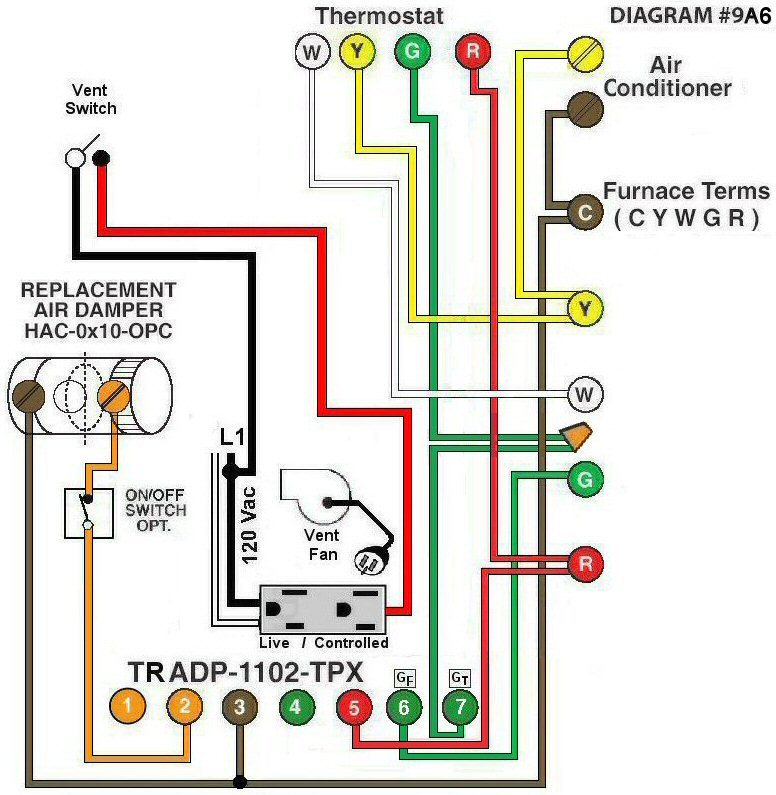
Diagram #9A6: Forced Air Furnace having a Replacement Air Supply Duct together with a Plug-In Exhaust Fan controlled by a designated Ventilation Switch and automatic Interval Timer for recycling the entire system
- Replacement Air Damper, Power Closed, (HAC-0x10-OPC) controls Fresh Air Inlet
- 120Vac Ventilation Switch controls the Receptacle Timer Adaptor (TRADP-1102-TPX) place in the Furnace area
- Plug-In Exhaust Fan controlled by the Adaptor
- Relay Adaptor with Interval Timer functions as the automatic control center
OPERATION:
- Furnace fires with Thermostat signal
- Ventilation Switch turns on the Ventilation Fan, opens Replacement Air Damper and turns on Furnace Fan simultaneously
- Interval Timer (Recycler) can be set for minimum or multiple consecutive settings of 15 minutes to simultaneously turn on the Ventilation Fan open Replacement Air Damper and turn on the Furnace Fan
- Optional switch (i.e. toggle switch, DE humidistat) connected between #2 of the Adaptor and the damper allows full control of the Power Close Replacement Air Damper to open as required
N.B. Replacement Air Damper is not affected by the ‘Manual’ setting of the Furnace Fan.