
Combustion Air Damper for Two Furnaces and Two Replacement Air Dampers (Power Close)
#2A1. Combustion Air Damper (HOM-0x12-SF2) interlocked to Two Furnaces and Interconnected to Two (HAC-0x10-OPC) Power Close Replacement Air Dampers that open for either Furnace.
HMI Hoyme Manufacturing Inc. Special Note: Circuits are colored for clarification only and are not necessarily those found in actual installations. Combustion Air Damper Wires, however, are colored as shown.
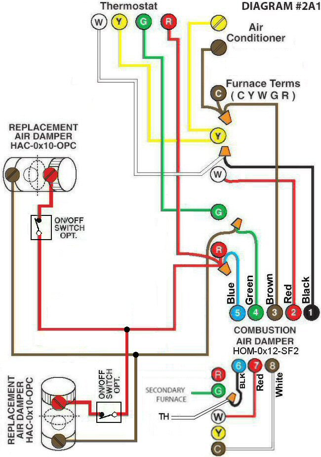
Diagram #2A1: Two Forced Air Furnaces having a Common Combustion Air Supply Duct and two separate Replacement Fresh Air Supply Ducts.
- Combustion Air Damper for two appliances*(HOM-0x12-SF2)* but having only one Combustion Air Supply Duct.* (This Damper has two separate operating circuits)*
- Replacement Air Dampers (HAC-0x10- OPC – Power Close) are inter-connected to each other and to the HOM
OPERATION:
Combustion Air Damper is interlocked to both appliances so that the Damper proves to be open to supply fresh air for combustion when either one or the other or both Furnaces are firing. Both HAC Replacement Air Dampers will also open when either Furnace fires. Air will be drawn in, however, only for the Furnace that is firing provided Furnace Circulation Fans run only when Furnaces fire.