
Vent Switch and Interlocking Replacement Air – Power Close:
#12. Forced Air Furnace with Power Close Replacement Air Damper (HAC-0x11-SPC) c/w Relay and End Switch that uses Adaptor (ADP-1102-TPX) to prove Replacement Air Damper is Open before Ventilation Fan and Furnace Fan run with Ventilation Switch and also opens during Furnace firing.
HMI Hoyme Manufacturing Inc. Special Note: Circuits are colored for clarification only and are not necessarily those found in actual installations. Combustion Air Damper Wires, however, are colored as shown.
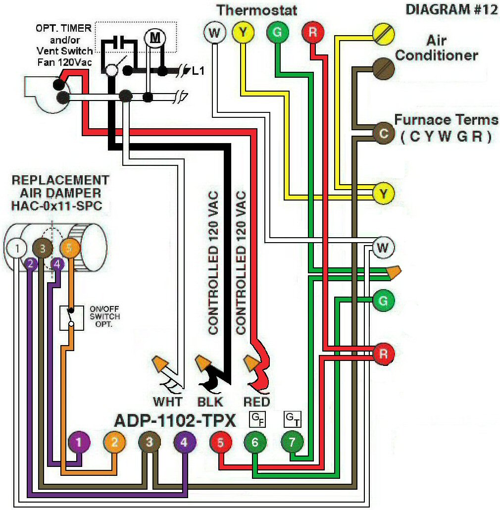
Diagram #12: Forced Air Furnace having a Replacement Air Supply Duct together with a designated Ventilation Switch and/or Bathroom Timer to turn on an Exhaust Fan INTERLOCKED to a Replacement Air Control Damper .
- Replacement Air Damper with Relay and End Switch (HAC-0x11-SPC)
- Ventilation Switch and/or bathroom timer with 3-Wire 120Vac supply to Furnace area
- Relay Adaptor (ADP-1102-TPX) functions as a control center
OPERATION:
- Replacement Air Damper opens during Furnace firing
- Ventilation Switch and/or Bathroom Timer opens the Replacement Air Damper. After Damper proves to be opened (INTERLOCKED), the Exhaust Fan and Furnace Fan will turn on
- Optional switch (i.e. toggle switch, timer, de-humidistat) allows full control of Replacement Air Damper to open at any time provided it is the PC type
N.B. Replacement Air Damper is not affected by the ‘Manual’ setting of the Furnace Fan.