
Replacement Air Damper Power Open with 120Vac Plug-In Vent Fan and Dampers controlled by Vent Switch:
#8A3. Forced Air Furnace With Combustion Air Damper (HOM-0x12-SF2) which also supplies Replacement Air For 120vac Gas Dryer using Adaptor (RADP-0241-S10A).
HMI Hoyme Manufacturing Inc. Special Note: Circuits are colored for clarification only and are not necessarily those found in actual installations. Combustion Air Damper Wires, however, are colored as shown.
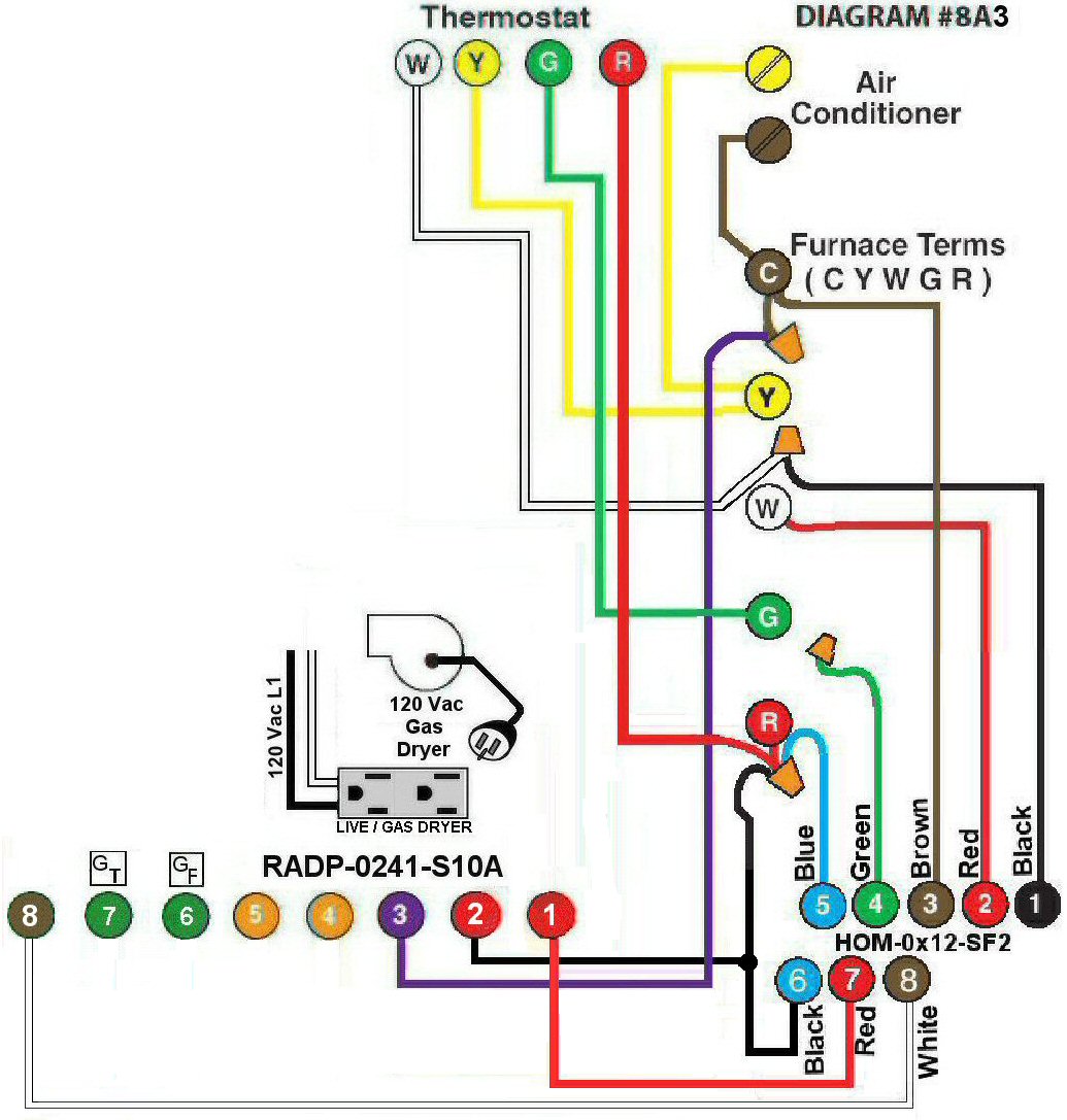
Diagram #8A3: Forced Air Furnace having a Combustion Air Supply Duct that also serves as a combustion air supply for a 120Vac Gas Dryer as a second appliance.
- Combustion Air Damper (HOM-0x12-SF2)
- 24Vac Relay Adaptor with a Duplex Receptacle and a Red Light on/off Switch (RADP-0241-S10A) to function as a control center interlocked to120Vac supply for a plug-in type Gas Dryer
OPERATION:
- Combustion Air Damper is interlocked to open for Furnace firing and/or to open for Fryer operation
- The Gas Dryer is plugged into the RADP-0241-S10A receptacle and will operate only after the Red Light Switch is turned on and the Combustion Air Damper is in the open position. When the Dryer has completed its cycle, the Adaptor Red Light Switch is to be turned off allowing the Combustion Air Damper to close
Note: Manual setting of the Furnace fan does not affect the Combustion Air Damper operation.
This installation does not interfere with the operation of the Air Conditioner.