
Two Vent Switches and interlocking Replacement Air Damper – Power Open – also opens on call for heat:
#12B4. Same as #12B3 but uses Adaptor (ADP-1103-TPX) with the Adaptor (ADP-1102-TPX) so Damper also Opens during Furnace firing.
HMI Hoyme Manufacturing Inc. Special Note: Circuits are colored for clarification only and are not necessarily those found in actual installations. Combustion Air Damper Wires, however, are colored as shown.
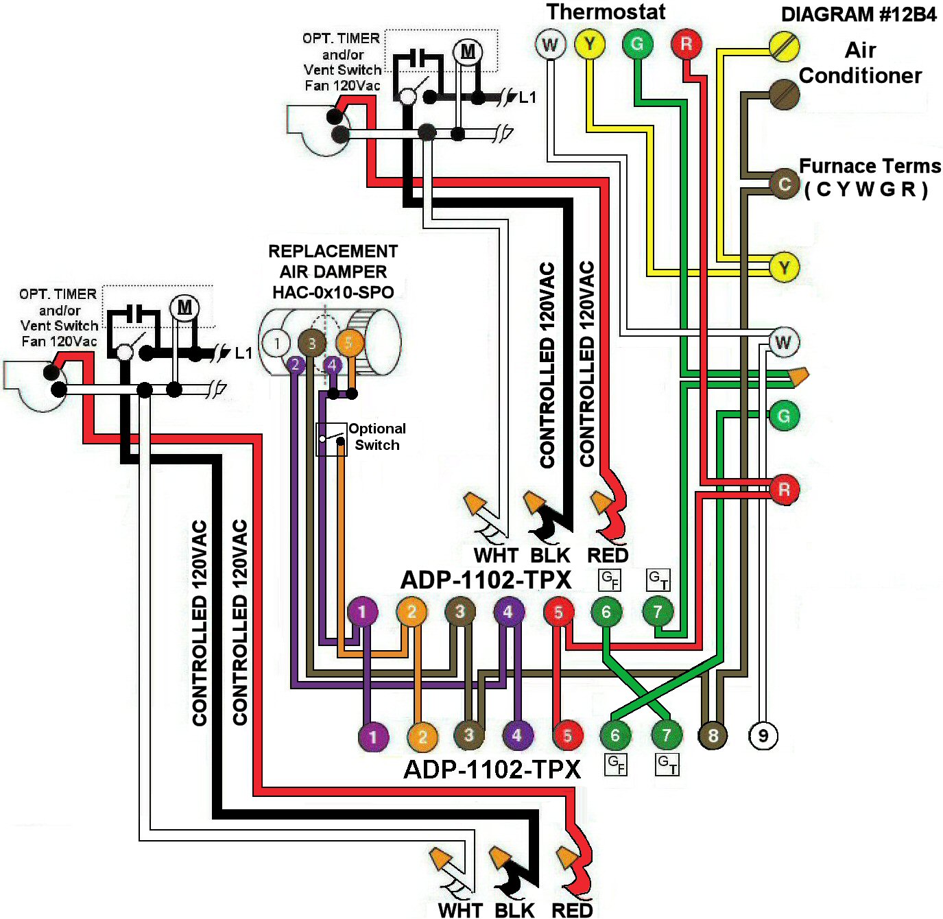
Diagram #12B4: Forced Air Furnace having a Replacement Air Supply Duct together with a designated ventilation switch and/or bathroom timer to turn on an Exhaust Fan INTERLOCKED to a replacement Power Open Air Control Damper.
- Replacement Power Open Air Damper and End Switch (HAC-0x10-SPO)
- Ventilation Switches and/or Bathroom Timers with 3-Wire 120Vac supply to Furnace area
- Relay Adaptors (ADP-1102-TPX) and (ADP-1103-TPX) function as control centers
OPERATION:
- Replacement Air Damper opens during Furnace firing
- Ventilation Switch and/or Bathroom Timer opens the Replacement Air Damper. After Damper proves to be open (INTERLOCKED), the Exhaust Fan and Furnace Fan will turn on
N.B. Replacement Air Damper is not affected by the ‘Manual’ setting of the Furnace Fan.
Also does not interfere with the Air Conditioner.