
Timer, Vent Switch, Replacement Air, Power Close, and an Exhaust Fan with 3-way Ventilation Switch:
#9C. Same as #9B But has a Designated Ventilation Switch which functions fully and also an additional 3-Way Switch to control Ventilation Fan only.
HMI Hoyme Manufacturing Inc. Special Note: Circuits are colored for clarification only and are not necessarily those found in actual installations. Combustion Air Damper Wires, however, are colored as shown.
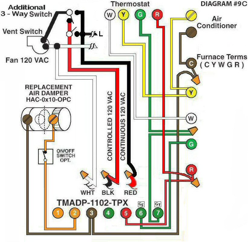
Diagram #9C: Forced Air Furnace having a Replacement Air Supply Duct and an Exhaust Fan controlled by a designated Ventilation Switch, a 3-way Ventilation Switch and an Interval Timer Adaptor.
- Replacement Air Damper , Power Close recommended, (HAC-0x10-OPC)
- Ventilation Switch supplies Controlled and Regular 120Vac (3-Wire) power to the Furnace area
- A 3-way Ventilation Switch to control Ventilation Fan only
- An Interval Timer Adaptor (TMADP-1102-TPX) which functions as a complete control centre
OPERATION:
- Furnace fires with Thermostat signal
- Ventilation Switch turns on Ventilation Fan, opens Replacement Air Damper and turns on Furnace Fan simultaneously
- Three-way Ventilation Switch turns on the Ventilation Fan only. (Not recommended unless living in coastal climates warmer than -10ºC and/or ample replacement air is supplied)
- Optional Switch (i.e. toggle switch, timer, de-humidistat) allows full control of Replacement Air Damper to Open as required provided it is a PC type
N.B. Replacement Air Damper is not affected by the ‘Manual’ setting of the Furnace Fan.