
HAC-F Installation Instructions – Printer Friendly(pdf)
Hoyme-HAC-F-General Information
Installation Instructions for HMI Hoyme Motorized Automatic Flue Damper – series ‘HAC-F” for Gas and Oil Burning Appliances
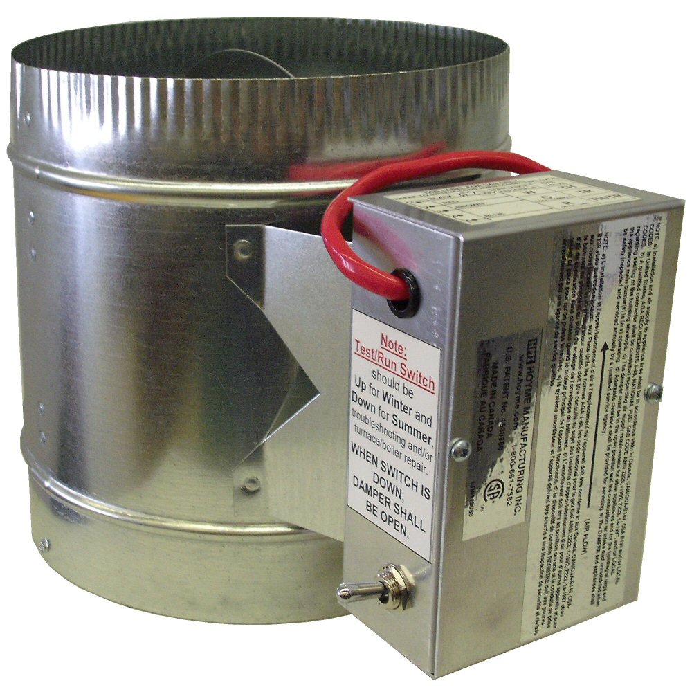 | 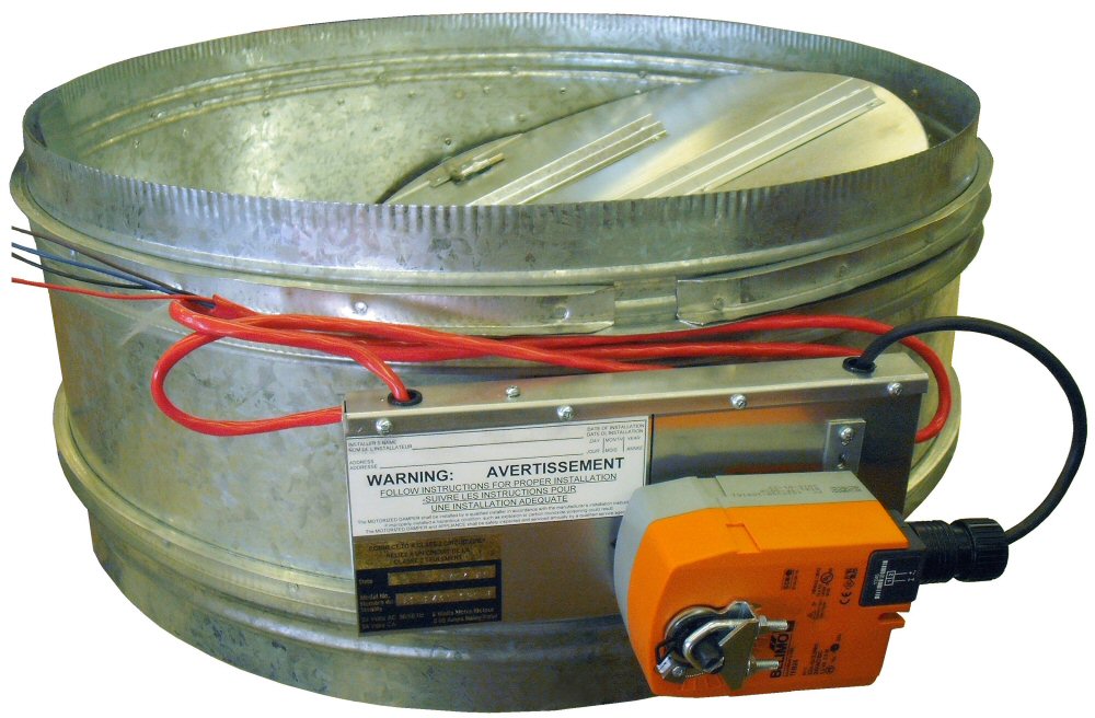 |
| HAC-F Damper Damper profile up to 9” diameter | HAC- F Damper Damper profile for 10” and over |
- This installation shall be subject to the approval of the enforcing authorities
- This Automatic Flue Damper saves energy and also protects the Heat Exchanger while the appliance is in the non-firing mode
- The Flue Damper stops the escape of warm air up the flue and at times, the reverse, stops cold air from coming down the flue
- Cold air not only wastes energy but also puts extra strain on appliance parts
- The damper comes with an End Switch so that the Damper proves to be open before the appliance fires. It is securely installed in the Flue Vent close to the appliance and matches the size of the factory built Flue.
- This Damper is Power Closed and has a Return Spring to fail-safe-open. On some heating appliances, the 24Vac supply turns off during the non-firing cycle or for OIL where ‘T’-‘T’ terminals are not identified. An Auxiliary Transformer (24Vac) is then used to keep the Damper closed
- If the Safety Circuit is not fuse protected, use the In-line Fuse and holder supplied. Part #3152-001 (See wiring diagram)
For COMMERCIAL installations having other than 24Vac, circuits, RELAY ADAPTORS are available to interface this Damper to a 250mVdc – 100Vdc and 120Vac Safety Control System
This installation shall be in accordance with: In Canada – CAN/CSA B149 & B139; In the USA – ANSI/NFPA 54, 2006, ANSI Z223.1 and/or local codes including local codes relating to Exhaust Vent Installation. A qualified contractor shall be consulted regarding the installation of this Damper
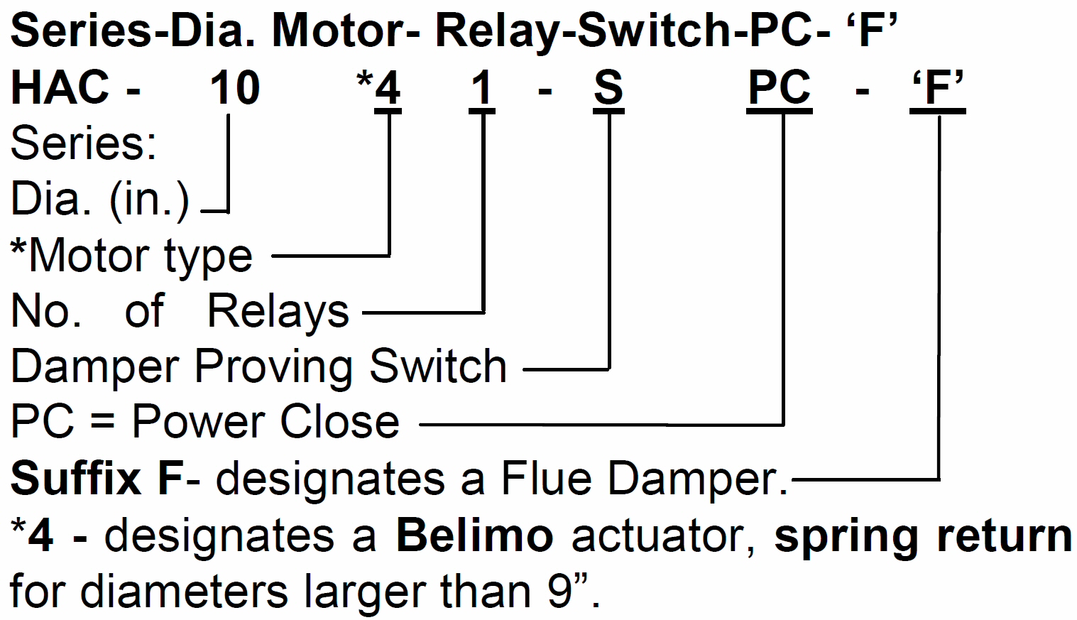 | Specifications: – Motor 24Vac – 5 Watts, 50/60 Hz – Relay Coil 0.05 Amps – Damper Identification having a 10″ dia – e.g.: HAC-1041-SPC – F |
AUTOMATIC FLUE VENT DAMPERS are designed to operate for years of trouble free service and are to be checked yearly for proper operation
ELECTRICAL WIRING shall be done in accordance with the National Electrical Codes or with Local Codes where they prevail. Additional wire shall be of the same size and type as used with existing control circuits. Wiring thereto shall be well secured and reasonably remote from any source of heat
INSTALLER must be a trained, qualified person. Labels and Damper position shall be readily visible when in the installed position
NOTE: Before interlocking this Damper to a Safety Control Circuit, the heating appliance is to be checked for proper operation, according it its manufacturer’s specifications and according to applicable codes
CONNECTING to 24Vac APPLIANCE CIRCUIT:
- To Terminal strip, use (‘W’ ‘R’ ‘C’) or
- To Gas Valve, use (‘TH’; ‘TH-TR’; ‘TR’)
- Set Thermo/Aqua-Stat (stat) down to the lowest setting and turn off electrical power supply
- Connect Damper BLUE wire (5) to the 24Vac transformer wire leading to the stat or ( ‘R’ on the terminal strip; or ‘TH-TR’ on the gas valve)
- Connect Damper BROWN wire (3) to transformer common or ( ‘C’ on appliance terminal strip or ‘TR’ on the gas valve )
- Test by turning on the power supply causing the damper to close. Turn off power supply
- Remove stat wire connected to ( ‘W’ on terminal strip or ‘TH’ on the gas valve) and connect this stat wire to the damper BLACK wire (1) using a wire nut. *See diagram regarding fuse protection
- Connect Damper RED wire (2) back to ( ‘W’ on the terminal strip or ‘TH’ on the gas valve)
- Turn on power supply and damper will close. Turn stat to call for heat. Damper will open and appliance will operate normally
- Sequence the appliance through at least three normal cycles to confirm proper operation
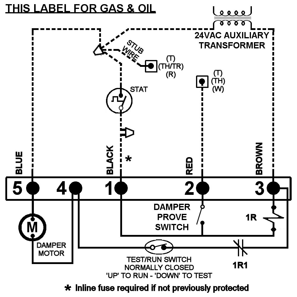
SCHEMATIC WIRING DIAGRAM OF FLUE VENT DAMPER and APPLIANCE TRANSFORMER
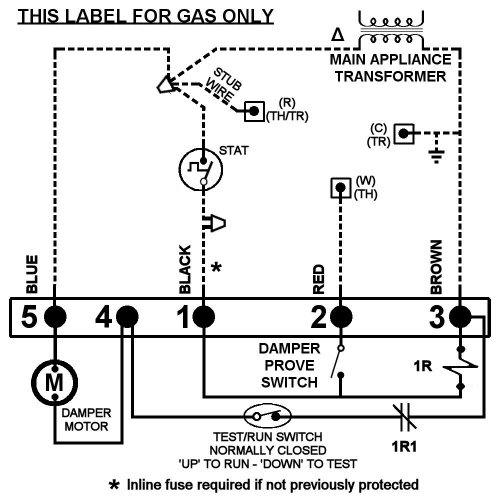
- Note: This marking is also on label to be affixed adjacent to appliance wiring diagram
- Typical location for 24Vac Limit Control when used in appliance circuit
- Circuit to be grounded if not previously grounded
- Affix appropriate labels and follow instructions and warnings on each label
- Always conduct a thorough check-out after installation is complete
- Damper type is Power Close and Spring Open
- Note: Test/Run Switch on the damper is to be in the up ‘Run’ position
AUXILIARY TRANSFORMER Connected to:
- Oil, use (‘T’ ‘T’) or
- Gas Valve, use (‘TH’; ‘TH-TR’) or
- Terminal strip, use (‘W’ ‘R’ ‘C’)
- (See Auxiliary Wiring Diagram on page 3)
Note: Test/Run switch on the damper is to be up in the ‘Run’ position
INSTRUCTION #9 explains proper phasing of 24 Vac transformer
- Turn stat to lowest setting
- Turn off electrical power supply. Install auxiliary transformer connected to appliance power supply
- Remove one stat wire from appliance (‘TH-TR’; or ’R’; or ’T’) and by using a wire nut, join four wires: Stat wire, Damper BLUE (5) wire, 24Vac auxiliary transformer wire and a 6” stub wire.Connect stub wire back to appliance stat terminal
- Connect Damper BROWN (3) wire to remaining 24Vac auxiliary transformer wire
- Test by turning on power supply. Damper will close. Turn off power supply
- Remove other stat wire from remaining appliance (‘TH’; or ‘W’; or ‘T’), and connect it to Damper BLACK (1) wire with wire nut supplied
- NOTE: In-line fuse to be connected here if circuit has not been previously protected.
- Connect Damper RED (2) wire back to appliance stat terminal (‘TH’ or ‘W’ or ‘T’)
- Turn on power supply to close Damper. If no action, interchange auxiliary transformer wires and retest
- PHASING of TRANSFORMERS : Jumper Damper (1) BLACK wire momentarily to Damper (2) RED wire. If Damper opens, an out-of-phase transformer is indicated. Correct by interchanging auxiliary 24Vac transformer wires and retest
- Turn stat to call for heat. Damper will open and heating appliance will operate normally
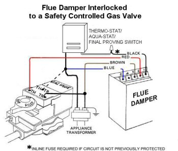
SCHEMATIC WIRING DIAGRAM OF FLUE DAMPER CONNECTED TO A 24Vac SAFETY CIRCUIT AND AN AUXILIARY TRANSFORMER.
- Note: This marking is also on label to be affixed adjacent to appliance wiring diagram
- A 3 amp fuse and fuse holder part #3152-001 is included if required
- Affix appropriate labels and follow instructions and warnings on each label
- Always conduct a thorough check-out after installation is complete
- Follow all applicable Codes
- Sequence the appliance through at least three normal cycles to confirm proper operation
General Information: The damper uses power to close when the appliance is not firing and cuts the power to the damper when the appliance is firing. This eliminates the damper overloading the appliance transformer during the firing cycle
General Wiring Information: Two wires from the Damper Motor are connected to the Appliance Transformer and two wires from the damper end switch are connected in series with the controlled stat wire
TROUBLESHOOTING PROCEDURE:
Condition: Damper does not open or fully open when the stat asks for heat
This indicates:
- Signal is not getting through from the stat to the damper
- Mechanical friction with motor, motor gears or rotor spring
- Broken damper return spring
Procedure
- Check in-line fuse (if used) between stat wire and damper black wire #1
- Remove cover and with a jumper wire join terminals 1 & 5. If damper opens, a faulty stat is suspected
- Turn Test/Run Switch to the ‘Test’ position and jumper terminals 1 & 2. If appliance does not fire, a faulty stat or stat circuit is confirmed
- If the damper has not been activated for a period of time, (e.g. summer months) the motor gears, being under continual pressure, might stick. If condition continues, replace motor.
- Motor gears wear with age causing increased friction which prevents the damper from opening freely. Replace motor
- Broken spring in the motor rotor. Remove broken spring with long nose pliers. The damper will continue to operate normally without the broken rotor spring
- Remove damper spring plate and replace with a new spring and plate
Condition: Damper does not close after appliance completes its firing cycle
Cause: Indicates
- Test/Run switch is not in the ‘run’ position
- A faulty relay
- No power supply
- A Faulty motor
Procedure
- Check Test/Run switch to be in the up ‘RUN’ position.
- Remove control body cover and use a jumper between terminals 3 & 4. If damper closes, a faulty relay is indicated
- Check power supply to terminals 3 & 5
- Connect power supply to terminals 4 & 5. No response indicates a faulty motor.
Condition: Damper opens on stat signal but appliance does not fire.
Cause: This indicates
- Appliance circuit faulty
- A faulty end switch
Procedure
- 1) The Flue Damper is interlocked with the heating appliance control system. This feature is by-passed by switching the TEST/RUN switch down to ‘TEST’ and putting a jumper to terminals 1 and 2. If heating appliance does not fire, a faulty heating safety circuit is suspected
- If appliance fires, a faulty end switch is suspected
Note: The TEST/RUN Switch is used for trouble shooting. It can also be left in the DOWN ‘TEST’ position during the summer months which will leave the damper continually open. This will leave the damper motor in neutral to extend the life of the motor
Hoyme-HAC-F-installation-instructions-1.pdf
Hoyme-HAC-F-General Information