
Forced Air Furnace with Combustion and Replacement Air Supply Ducts – Power Close Replacement Air Damper also opens on cooling cycle:
#8D2. Forced Air Furnace with Combustion Air Damper (HOM-0x11-SF1) and a Power Close Replacement Air Damper (HAC-0x10-OPC) that uses Adaptor (ADP-0241-05A) to Open Replacement Air Damper during both Heating and Cooling Cycles and to Open Combustion Air Damper During Furnace firing.
HMI Hoyme Manufacturing Inc. Special Note: Circuits are colored for clarification only and are not necessarily those found in actual installations. Combustion Air Damper Wires, however, are colored as shown.
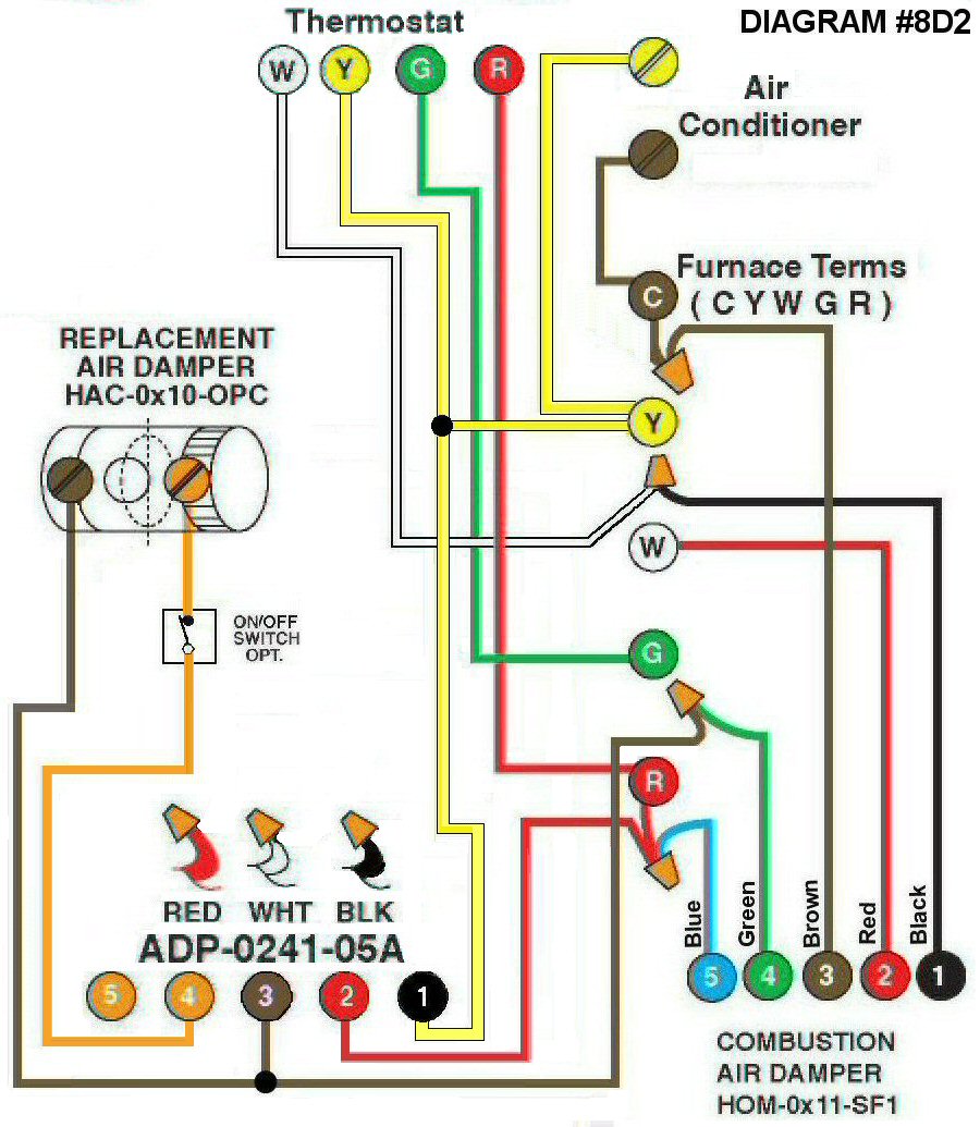
Diagram #8D2: Forced Air Furnace with a Fresh Air Supply Duct for Combustion Air and a Replacement Air Supply Duct.
- Combustion Air Damper (HOM-0x11-SF1)
- Replacement Air Damper, Power Close (HAC-0x10-OPO)
- 24Vac Relay Adaptor (ADP-0241-05A) to operate the Damper on the cooling cycle
OPERATION:
- Combustion and Replacement Air Dampers open during Furnace firing
- The Power Close (PC) Replacement Air Control Damper also opens on the cooling cycle
- Optional switch (i.e. toggle switch, timer, de-humidistat) provides full control of Replacement Air Damper to open as required
N.B. Replacement Air Damper is not affected by the ‘Manual’ setting of the Furnace Fan.