
Domestic Hot Water with Power Vent, Combustion Air Damper:
#11B. Domestic Hot Water Tank with Combustion Air Damper (HOM-0x11-SF1) c/w End Switch that uses Adaptor (ADP-1102-S5A) to prove Combustion Air Damper is Open before Power Vent runs.
HMI Hoyme Manufacturing Inc. Special Note: Circuits are colored for clarification only and are not necessarily those found in actual installations. Combustion Air Damper Wires, however, are colored as shown.
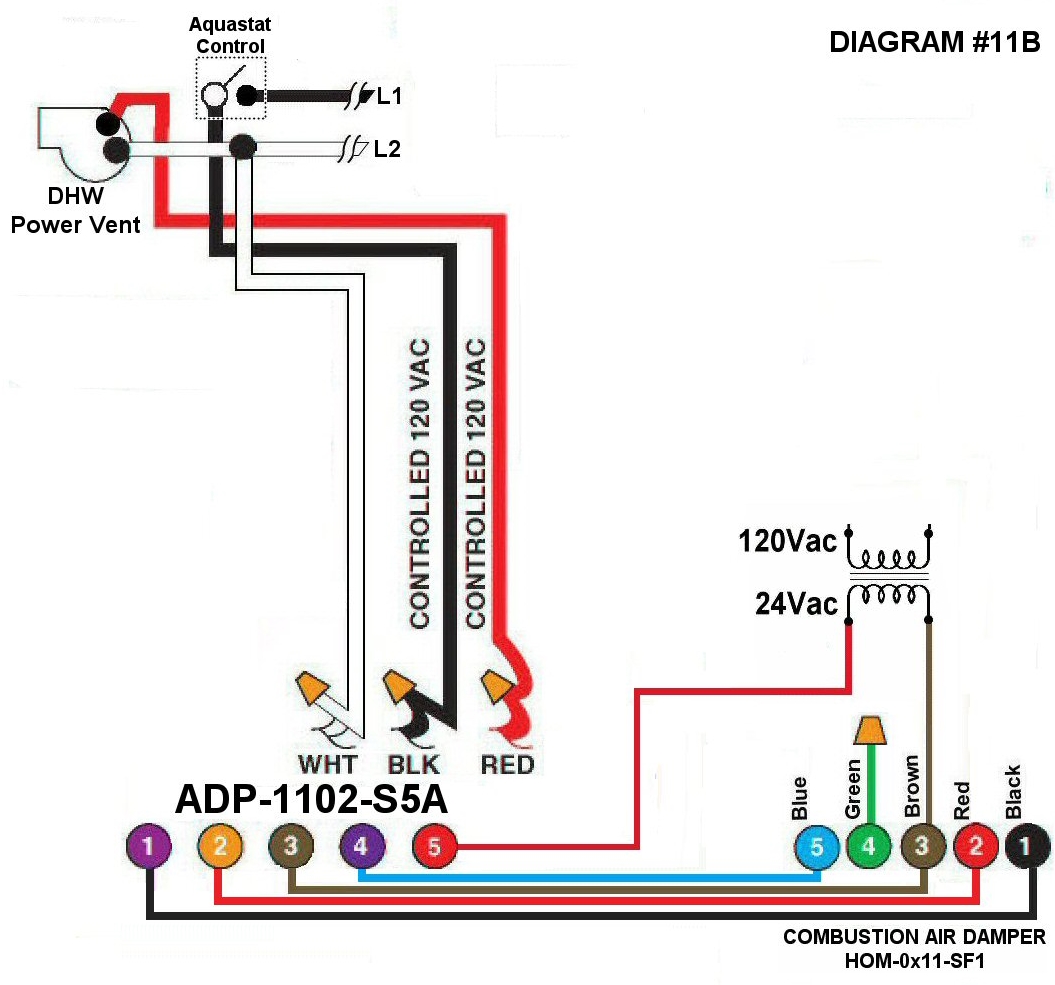
Diagram #11B: Domestic Hot Water with Power Vent having a Combustion Air Supply Duct. Damper is INTERLOCKED to prove to be open before Power Vent Fan runs.
- Combustion Air Damper (HOM-0x11-SF1)
- Interface Relay Adaptor (ADP-1102-S5A) functions as a control center
- Continuous 24Vac power supply
OPERATION:
- Power Vent signal from hot water tank directed to Relay adaptor to open the Damper
- After Damper proves to be opened (INTERLOCKED), the Power Vent Fan will turn on