
Timer, Vent Switch, and Replacement Air Damper – Power Close:
#9A. Identical to #9 but minus the Combustion Air Damper (HOM-0x11-SF1).
HMI Hoyme Manufacturing Inc. Special Note: Circuits are colored for clarification only and are not necessarily those found in actual installations. Combustion Air Damper Wires, however, are colored as shown.
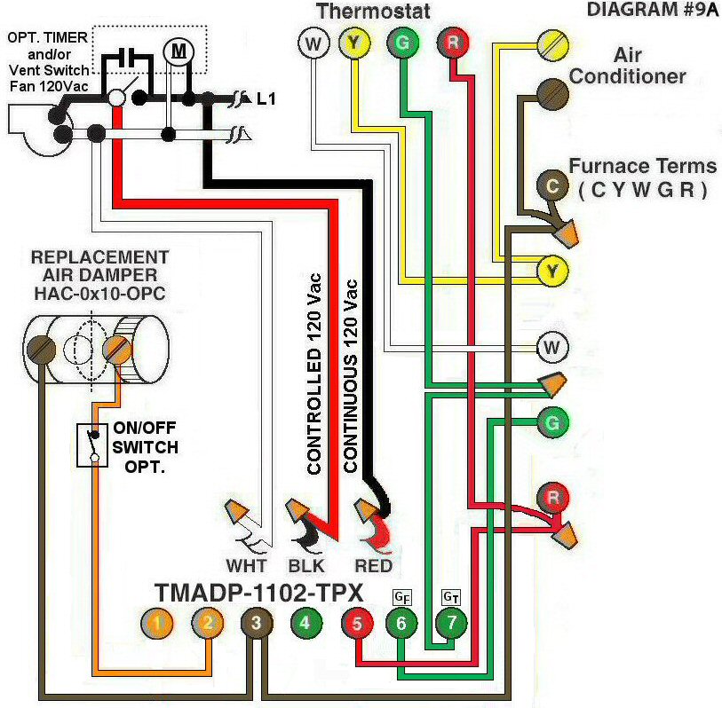
Diagram #9A: Forced Air Furnace having a Replacement Air supply Duct together with an Exhaust Fan controlled by a designated Ventilation Switch and/or an optional Bathroom Timer and an Interval Timer.
- Replacement Air Damper, Power Close recommended, (HAC-0x10-OPC) to control Fresh Air Inlet
- Ventilation Switch and /or an optional Bathroom Timer supply a Controlled and a regular 120Vac 3-wire power supply to the Furnace area
- Relay Adaptor with Interval Timer (TMADP-1102-TPX) functions as the automatic control centre
OPERATION:
- Furnace fires with Thermostat signal
- Ventilation Switch and/or Bathroom Timer turns on Ventilation Fan, opens Replacement Air Damper and turns on Furnace Fan simultaneously
- Interval Timer can be set for minimum or multiple consecutive settings of 15 minutes to simultaneously turn on Ventilation Fan open Replacement Air Damper and turn on the Furnace Fan
- Optional switch (i.e. toggle switch, timer, de-humidistat) allows full control of the PC Replacement Air Damper to open as required
N.B. Replacement Air Damper is not affected by the ‘Manual’ setting of the Furnace Fan.