
HOM Commercial Combustion Air Damper Installation Instructions – Printer Friendly(pdf)
Installation Instructions for HMI Hoyme Motorized Commercial ‘HOM’ Dampers in Modules For Appliances Having Inputs Exceeding 400,000 BTU (117.23Kw):
- This Installation Shall be in Accordance with the Requirements of the Authorities having Jurisdiction.
- The HOYME Combustion Air Control Damper may be arranged in Modules and field installed where the demand for combustion air exceeds the area of one Damper.
Installer must be an experienced trained service person thoroughly familiar with the following “Installation Instructions for Hoyme”:
- Motorized Combustion Air Control Damper – Vertical Mount – 24Vac
- ADP-1102, 120Vac Interlocks 24Vac Combustion Air Control Damper to Line Voltage120Vac Safety Control Circuits
- Adaptor 0MV2, Interlocks 24Vac Combustion Air Control Damper to a 250mVdc – 100Vdc Safety Control System
- Adaptor 0241, 24Vac Controlled Voltage-Switches 120Vac
- Adaptor 1101, 120Vac Controlled Line Voltage – Switches 24Vac
- Motorized Replacement/Ventilation Air Control Dampers
Installer will also:
- Follow installation instructions, specifications and labels.
- Refer to: CAN/CSA B149, CSA B139; In USA, NFPA54, 2006, ANSI Z223.1, and/or local codes regarding air supply requirements for installations greater than 400,000 BTUH (117.23 Kw) input.
- Check capacity of Appliance Transformer.(Motor-5 watts, Relay coil-0.05 Amps.)
- Where an Auxiliary Transformer is required, the Installer shall provide an approved 24Vac 50/60 -Hz. Transformer of adequate capacity.
- Supply for the Transformer primary shall be taken from the line voltage supply for the appliance. Refer to applicable Codes.
- Always conduct a thorough check-out after installation is complete.
- Affix Wiring Diagram label together with other applicable labels to the appliance.
| Typical Module of Dampers Mounted on a Combustion Air Supply Duct | Manifold openings are to be spaced a minimum of 2″ for Damper clearance | |
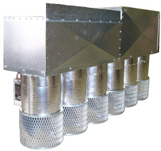 |  |
- Calculate number and size of Dampers required in modules to satisfy national and local codes.
- Interconnect Dampers Type SF1 or Type SF2, (as these are the only ones of the Module to be connected directly to the appliance), to the appliance Safety Control Circuit as per installation instructions supplied with each
- Choose the proper Damper-module combination of size and circuits. Refer to Wiring Diagram Type SF1, S01 and S02 for proper interconnection. All Damper Proving switches shall be connected in series to each other so that Dampers prove to be open before appliance fires
- Where required, install a 24VAC Auxiliary Transformer of sufficient capacity and connect to terminals 3 and 5. Note: Auxiliary Transformer must be connected in phase with existing Appliance Transformer. Check by momentarily touching Auxiliary Transformer wires to Appliance Transformer wires. Excessive sparking indicates an out-of-phase conditional exchange Auxiliary Transformer wires and connect to proper terminals 3 and 5
- Connect Terminals 3, 4 and 5 to succeeding dampers as per wiring diagram
- Turn on power supply. All Dampers will close
- If used, an inline fuse (factory part #3152-001) is to be connected in series with Terminal #1 of the primary Damper
- Turn stat to call for heat. Damper modules will open and appliance will operate normally.
Note: ‘TEST/RUN’ Switch on primary Damper is to be ‘UP’ for normal operation and shall be ‘DOWN’ for test purposes or for Dampers to remain open i.e. summer operation.
Schematic Wiring Diagram Interconnecting Hoyme Modules to Appliances Having Inputs Exceeding 400,000 BTUH (117.23 Kw):
Motor 5 Watts. Relay 0.05 Amps. Note: This marking is also on label to be affixed Adjacent to appliance wiring diagram.
For more information, please contact HMI HOYME Manufacturing Inc. @ 1-800-661-7382, or www.hoyme.com
HOM Commercial Combustion Air Damper Installation Instructions – Printer Friendly(pdf)