
Replacement Air Damper Power Open with 120Vac Plug-In Vent Fan and Dampers controlled by Vent Switch:
#8A2. One Power Open Replacement Air Damper (-PO), One Adaptor (RADP-0241-10A) c/w 120vac controlled Receptacle, Two 24vac transformers, Two Power Open Air Dampers (HAC-0x10-SPO) c/w End Switches to Control Adaptor.
HMI Hoyme Manufacturing Inc. Special Note: Circuits are colored for clarification only and are not necessarily those found in actual installations. Combustion Air Damper Wires, however, are colored as shown.
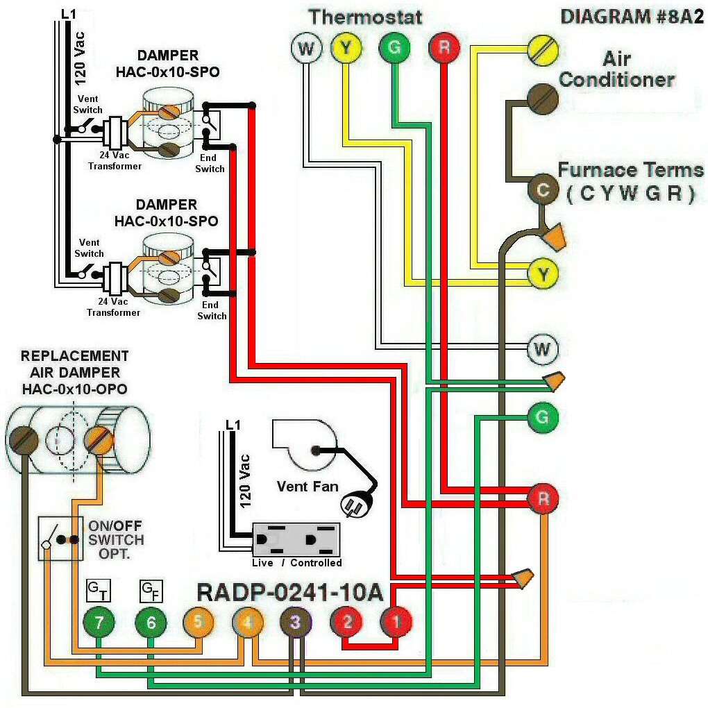
Diagram #8A2: Forced Air Furnace having a Replacement Air Supply Duct together with a plug-in type Exhaust Fan venting two bathrooms equipped with 24Vac Control Dampers.
- Replacement Air Control Damper, Power Open (HAC-0x10-OPO)
- Damper(s) with End Switch (HAC-0x10-SPO) controlled with a 24Vac Transformer from each bathroom
- 24Vac Relay Adaptor with Duplex Receptacle (RADP-0241-10A) to function as a control center supplying 120Vac for a plug-in type Exhaust Fan
OPERATION:
- Furnace fires with Thermostat signal
- 24Vac damper with end switch simultaneously turns on Furnace Fan, opens Replacement Air Damper and supplies 120Vac to the controlled side of the Duplex Receptacle for the plug-in type Exhaust Fan
- Optional Switch (i.e. toggle switch, de-humidistat) allows full control of Replacement Air Damper to open as required
N.B. Replacement Air Damper is not affected by the ‘Manual’ setting of the Furnace Fan