
Installation instructions – Printer friendly (pdf)
TMADP-1102-TPX – Information Page
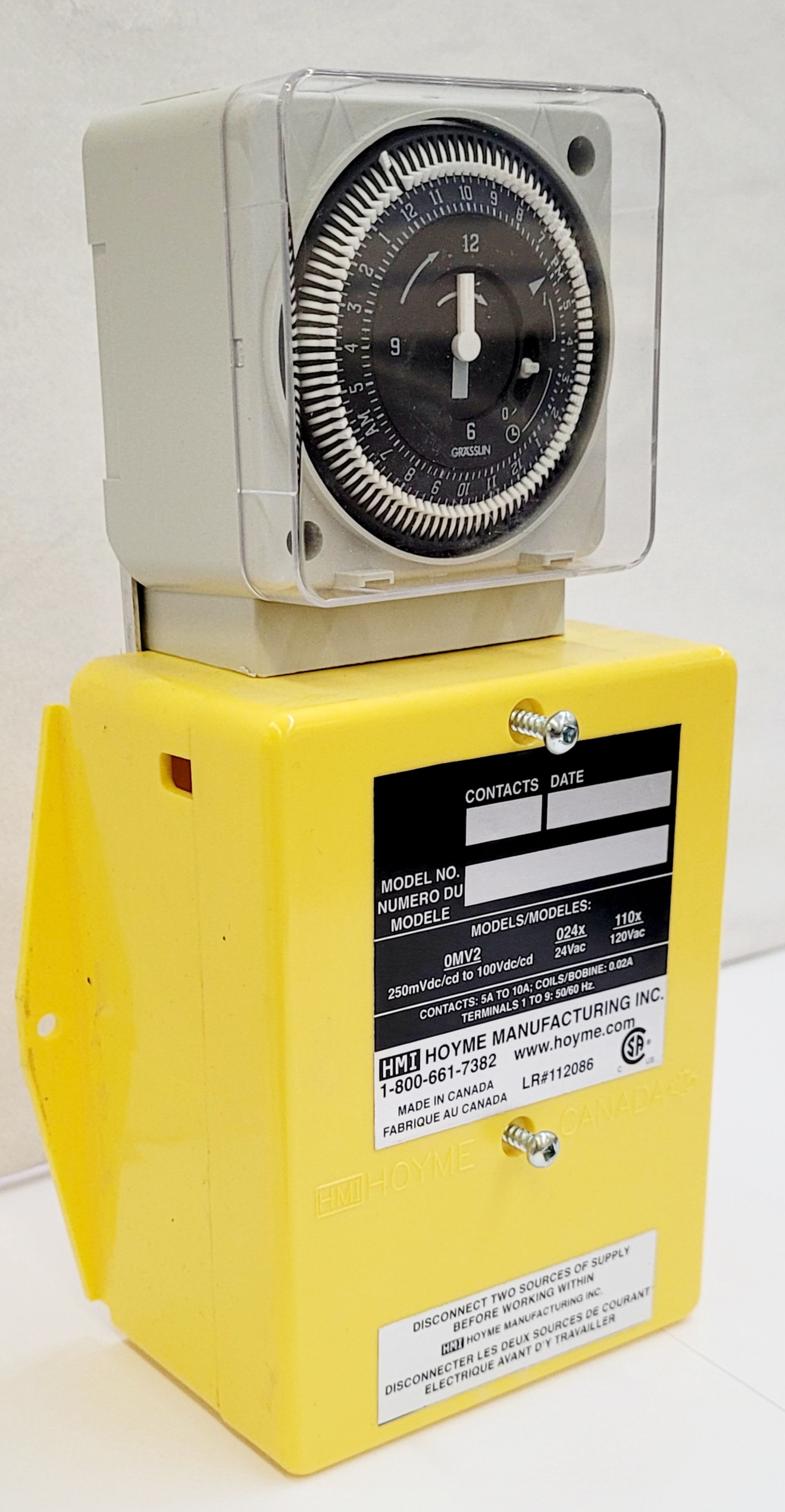
Installation Instructions for HMI HOYME TMADP – 1102 – TPX
- 4”x8 1/4”x2 1/2” – 101x 206 x 64mm
- Interconnects 24Vac Interval Timer and/or 120Vac Manual Switch to:
- Exhaust Fan, Furnace Circulation Fan and Fresh Air Inlet Damper
- Relay Coils: One-120Vac and One-24 Vac. Contact Points: 10/5 Amps
- Installation Of This Adaptor Shall Be In Accordance With The Requirements Of the Authorities Having Jurisdiction
- This TMADP-1102 adaptor with two relays and a 24Vac interval timer, together with a central ventilation switch, acts as an automatic/manual control centre to simultaneously start a principal exhaust fan, turn on a furnace fan, and open a fresh air inlet damper (If used)

Refer also to HMI Installation Instructions:
- ADP-1102-TPX
- ADP-1102-S5A
- ADP-1101-05A
- ADP-0241-05A.
- TMADP-1102-TPX
This TMADP-1102 adaptor with two relays and a 24Vac Interval Timer, together with a Central Ventilation Switch, acts as an automatic/manual control centre to simultaneously start a principal exhaust fan, turn on a furnace fan, and open a fresh air inlet damper (If used).
Fitness of this Timer/Adaptor combination to satisfy air supply requirements for fuel fired appliances during operation of the inter-connected exhaust fan(s) shall be investigated by the enforcing authorities.
Air Intake Duct Installation shall be in accordance with: In Canada – CAN/CSA B149 & B139; In the USA – ANSI/NFPA 54, 2006, ANSI Z223.1 and/or local codes including local codes relating to Ventilation Air Duct Installation.
I.D.: TMADP -1102 -TPX comes with 24Vac Interval Timer;
- 1 relay: Coil -120Vac, Contacts 5 Amps
- 1 relay: Coil – 24Vac, Contacts 10 Amps
Requirements
- Adaptor line voltage leads connected to the appliance controlled line voltage shall be suitably cabled, fastened and enclosed in suitable raceways
- Refer to local and applicable codes
- Always conduct a thorough checkout after installation is complete
- Affix appropriate labels and follow instructions and warnings on each label
Installation
- Turn thermostat to lowest setting
- Turn off electrical power to furnace
- Turn off electrical power to exhaust fan circuit
- Select suitable location for TMADP-1102-TPX
Connecting Adaptor to 24Vac Circuit:
- Connect
- TMADP terminal 5 to Furnace R
- TMADP terminal 3 to Furnace C; and
- TMADP terminal 6(GF) to Furnace G
NOTE: If thermostat wire G is connected to Furnace G, disconnect it from Furnace G and reconnect it to TMADP 7(GT) Then connect TMADP 6(GF) to furnace G.
Connecting Adaptor to 120Vac Circuit:
- Connect:
-TMADP RED wire to 120Vac live
-TMADP BLACK wire to controlled side of fan switch
-TMADP WHITE wire to 120Vac common - Follow applicable codes
- Mount inlet Damper in a suitable location on the return plenum and fasten inlet duct to the damper. Damper may also be placed in-line with inlet duct. Connect the two motor wires to
- TMADP terminals 3 & 1 for Power Open damper
– or –
TMADP terminals 3 & 2 for Power Close Damper
TIMER: Set cycles as per instructions with it - Turn on 120Vac power supply to Exhaust Fan and 120Vac power supply to furnace
- Turn on manual exhaust fan switch. Exhaust Fan, Furnace Circulation Fan (if not running) and damper will respond simultaneously. Turn off Exhaust Fan Switch
- Turn Interval Timer clockwise through one full turn (24 hrs) to test chosen settings. Exhaust Fan, Furnace Circulation Fan and damper will respond simultaneously for each setting. Set timer for time of day
- Turn thermostat to normal setting and furnace will operate normally
Note: Use TMADP-1103-TPX and follow its Installation Instructions if Inlet Damper is to Open also during furnace firing
Schematic Wiring Diagram of TMADP-1102-TPX
Interconnected to Furnace Circulation Fan Control, Principle Exhaust Fan and Motorized Fresh Air Inlet Damper
Note: this marking is also on label to be affixed adjacent to appliance wiring diagram
Additional wire shall be of the same size as originally used when completing electric circuits
For more information, please contact HMI HOYME Manufacturing Inc. @ 1-800-661-7382
Installation instructions – Printer friendly (pdf)
TMADP-1102-TPX – Information Page