
120 Vac Two Double Pole Vent Switches with Two Exhaust Fans, Combustion Air and Replacement Air:
#5C. 120vac Two Double Pole Ventilation Fan Switches with Two Exhaust Fans, Combustion Air Damper and Power Close Replacement Air Damper (-PC).
HMI Hoyme Manufacturing Inc. Special Note: Circuits are colored for clarification only and are not necessarily those found in actual installations. Combustion Air Damper Wires, however, are colored as shown.
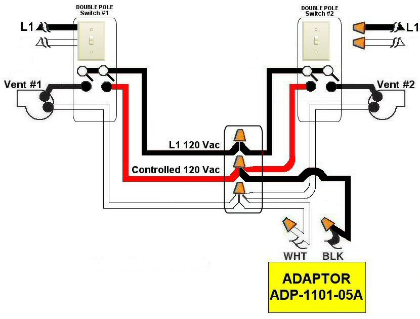
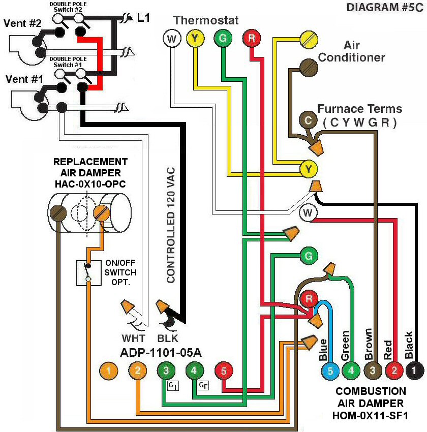
Diagram #5C: Forced Air Furnace having a Combustion Air and a Replacement Air Supply Duct together with two Exhaust Fans controlled by two separate Double Pole Ventilation Switches.
- Combustion Air Damper (HOM-0x11-SF1)
- Replacement Air Damper (HAC-0x10-OPC)
- Two Ventilation Switches (DP) to supply controlled 120Vac
- Relay Adaptor (ADP-1101-05A) which functions as a control center
OPERATION:
- Combustion Air Damper and Replacement Air Damper open during Furnace firing
- Either Ventilation Switch turns on Exhaust Fan, opens Replacement Air Daper and turns on Furnace Fan simultaneously.
- Optional Switch (i.e. toggle switch, timer, de-humidistat) provides full control of Replacement Air Damper to open separately provided the Damper is the Power Close(PC) type
N.B. Replacement Air Damper is not affected by the ‘Manual’ setting of the Furnace Fan.