
Installation instructions – Printer friendly (pdf)
ADP-1102-TWP – Information Page
Installation Instructions for HMI HOYME Adaptor 1102-TWP
120Vac Controlled Line Voltage to Switch 24Vac
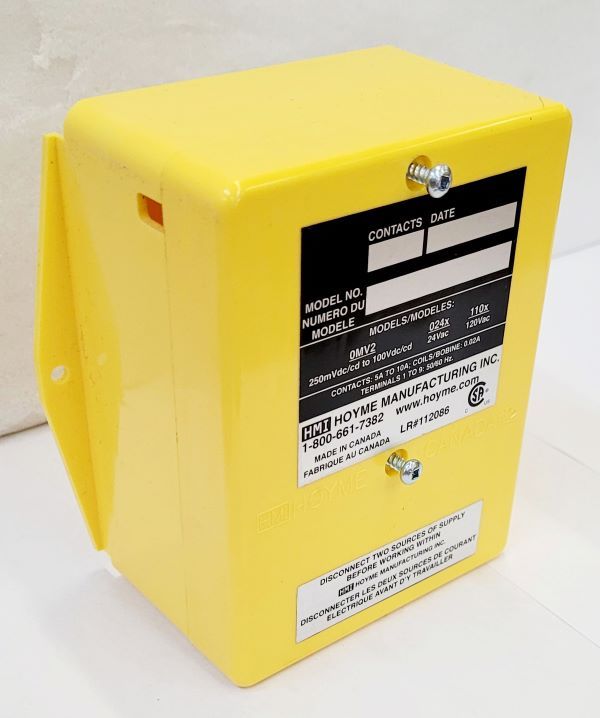
- 4” x 5” x 2 1/2” (101 x 127 x 64 mm)
- This Adaptor is an automatic switch to open a 24Vac Replacement /Ventilation damper during the ventilation cycle of the furnace
- By connecting the Adaptor 120Vac Relay Coil to the controlled line voltage of an Exhaust Fan and connecting the 24Vac circuit to the Furnace Terminals, the Exhaust Fan, the Furnace Fan and the Inlet Damper will all operate simultaneously
- The Inlet Damper may also be connected to open during the firing cycle of the furnace

Installation Of This Adaptor Shall Be In Accordance With The Requirements Of the Authorities Having Jurisdiction
Refer also to HOYME Installation Instructions: Combustion Inlet Air Control Damper, Series HOM; Replacement/Ventilation Air Control Damper – HAC; ADP-1101-05/10A and ADP- 0241- 05/10A
Fitness of this Adaptor/Damper combination to satisfy air supply requirements for fuel fired appliances during operation of the interconnected exhaust fan(s) shall be investigated by the enforcing authorities.
Air Intake Duct Installation shall be in accordance with: In Canada – CAN/CSA B149 & B139; In the USA – ANSI/NFPA 54, 2006, ANSI Z223.1 and/or local codes including local codes relating to ventilation air duct installation.
- I.D: ADP -1102 – TWP
- 1 – DPDT Relay Coil -120Vac Points – 24Vac – 5A
- 1- SPDT Relay Coil – 24Vac Points – 24Vac – 5A
Requirements
- Adaptor line voltage leads, connected to the exhaust fan controlled line, shall be suitably cabled, fastened and enclosed in suitable raceways
- Always refer to local and applicable codes
- Always conduct a thorough check-out after installation is complete
- Affix appropriate labels and follow instructions and warnings on each label
Installation
Connecting the Adaptor ADP-1102-TWP to a controlled 120Vac Designated Ventilation Exhaust Fan circuit, to the heating appliance and to a 24Vac Inlet Damper:
- Install Motorized Air Control Damper as per instructions supplied with it
- Turn off electrical power supply to appropriate appliance(s)
- Connect Adaptor line voltage leads to the controlled exhaust fan circuit as per wiring diagram.
- Follow applicable codes
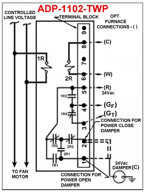
- Connect the Adaptor Terminal #5 to furnace Terminal ‘R’
- (a) If the Inlet Damper is a Power Close type, connect one damper wire to Adaptor Terminal #2 and the other damper wire to furnace ‘C’
- (b) If Inlet Damper is Power Open type, then connect one wire to Adaptor Terminal #1 and the other wire to furnace ‘C’
- Connecting Furnace Circulation Fan to operate during Exhaust Fan Cycle: This installation will not interfere with A/C circuits
- (a) Disconnect the thermostat wire ‘G’ (if used) from the furnace Terminal ‘G’ and connect it to the Adaptor terminal #3(GT)
- (b) Connect Adaptor Terminal #4(GF) to the furnace ‘G’
- Turn on electrical line power to appliance(s). If damper is a Power Open type, it will remain Closed at this time. If damper is a Power Close type, it will close at this time
- Turn on Exhaust Fan Switch. Exhaust fan, Furnace Fan and Inlet Damper will operate simultaneously
If Damper is to Open during Firing of the Furnace:
- Connect Adaptor #6 to Furnace ‘W’ and Adaptor #8 to furnace ‘C’. Damper will remain open during firing for complete combustion and will Close to save energy when furnace fire stops
Additional wire shall be of the same size as originally used when completing electric circuits
Schematic Wiring Diagram – ADP-1102-TWP
Note: This marking is also on label to be affixed adjacent to appliance wiring diagram
For more information, please contact HMI Hoyme Manufacturing Inc. @ 1-800-661-7382
Installation instructions – Printer friendly (pdf)
ADP-1102-TWP – Information Page