
Combustion Air Damper for Two Furnaces and Two Replacement Air Dampers (Power Close with Relays):
#2B1. Combustion Air Damper (HOM-0x12-SF2) Interlocked to Two Furnaces and Interconnected to Two Separate (HAC-0x11-OPC) Power Close Replacement Air Dampers c/w Relays to Open during Furnace firing.
HMI Hoyme Manufacturing Inc. Special Note: Circuits are colored for clarification only and are not necessarily those found in actual installations. Combustion Air Damper Wires, however, are colored as shown.
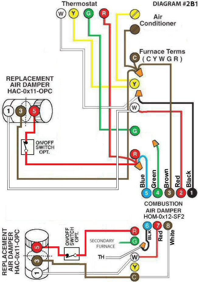
Diagram #2B1: Two Forced Air Furnaces having a common Combustion Air Supply Duct and two separate Replacement Fresh Air Supply Ducts.
- Combustion Air Damper for two appliances* (HOM-0x12-SF2)* but having only one Combustion Air Supply Duct.* (Damper has two separate operating circuits)*
- Two Power Close Replacement Air Dampers with a Relay (HAC-0x11-OPC) and each one inter-connected to its own furnace
OPERATION:
Combustion Air Damper is interlocked to both appliances so that the damper proves to be open to supply fresh air for combustion when either one or the other or both furnaces are firing. Each Replacement Air Damper opens simultaneously only with the firing of its own furnace but will remain closed regardless of furnace fan operation. Dampers may be opened on demand by using an optional overriding switch as shown.