
Installation instructions – Printer friendly (pdf)
RADP-0241-10A – Information Page
Installation Instructions for HMI HOYME RADP-0241-10A
- 4” x 5” x 2 ½” (101 x 127 x 64 mm)
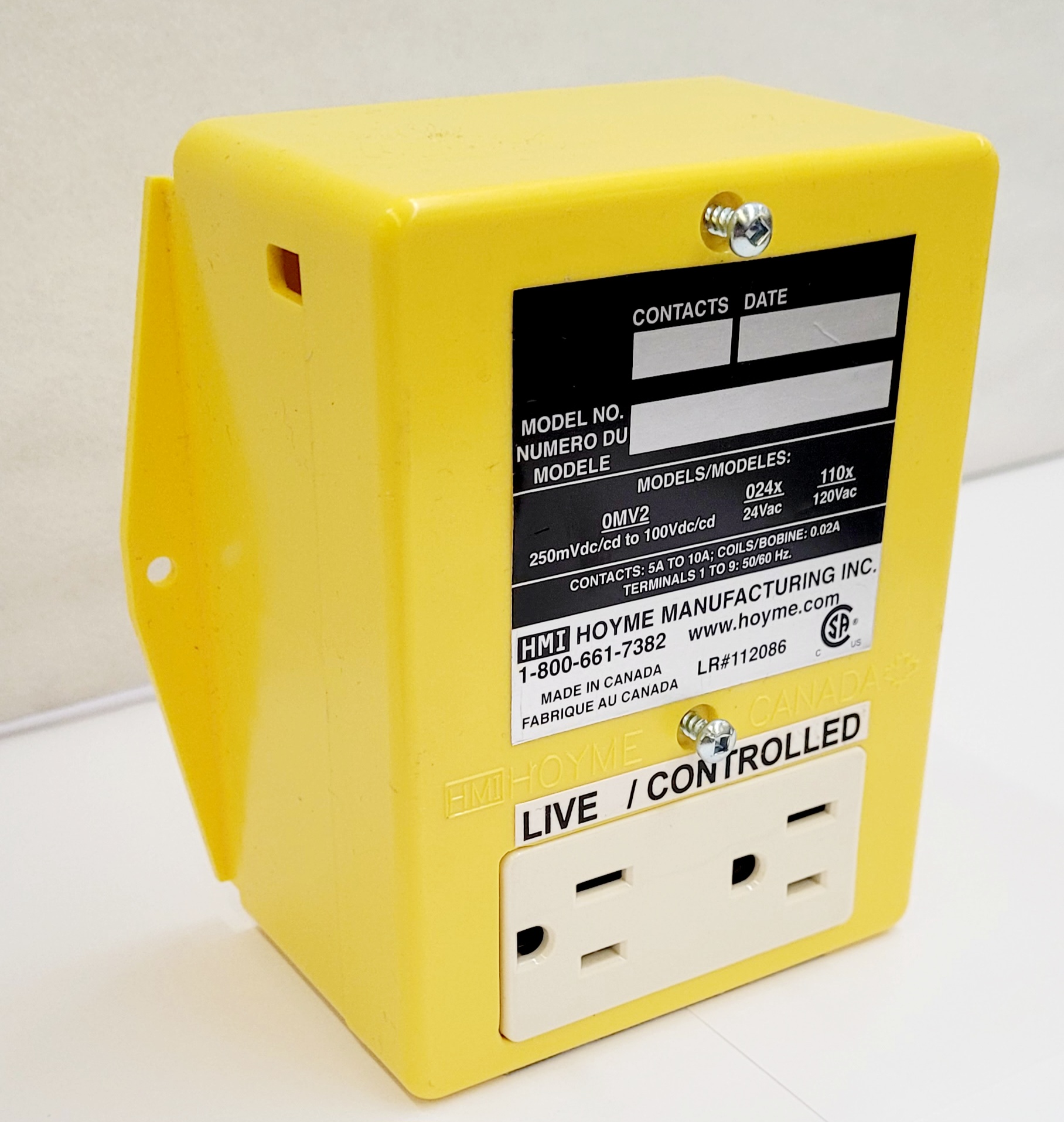
- Duplex Split Receptacle- (one side Live and one side Controlled)
- Fitness of this Adaptor/Damper combination to satisfy air supply requirements for fuel fired appliances during operation of the interconnected exhaust fan(s) shall be investigated by the enforcing authorities

- This Interface Adaptor comes with a Relay 24Vac Coil SPDT to develop a 10A contact capacity and a Relay 24Vac Coil DPDT to develop multiple contact points together with a split Duplex Receptacle. The split Receptacle provides a controlled plus a continuous 120Vac power supply outlet
- The two 24Vac Coils are connected in parallel and therefore act as one relay. This Adaptor allows for a 24Vac circuit such as a furnace safety control circuit or a 24Vac damper with end switch to control a 120Vac PLUG-IN Fan for ventilation, zone control or fresh air control
- Installation of this Adaptor shall be in accordance with the requirements of the authorities having jurisdiction
- Air intake duct installation shall be in accordance with: In Canada – CAN/CSA B149 & B139; In the USA -ANSI NFPA 2006, ANSI Z223. 1 and/or local codes including local codes relating to Ventilation Air Duct Installation
I.D.: RADP-0241-10A
- Includes 2 Relays with 24Vac Coils in parallel and acting as one relay
- 1 Relay SPDT: Coil-24Vac. Points-120Vac-10A
- 1 Relay DPDT: Coil-24Vac, Points-24Vac- 5A
- 1-Split Duplex Receptacle
Requirements
- If connecting to a heating appliance, use one Adaptor only for each appliance
- Line voltage leads, connected to the Adaptor shall be suitably cabled, fastened and enclosed in suitable raceways
- Refer to local and applicable codes
- Always conduct a thorough check-out after Installation is complete
- Affix appropriate labels and follow Instructions and warnings on each label
NOTE: The following hook-up procedures are suggestions and do not limit the uses of the Adaptor
- Turn off electrical power supply to both the appliance and the power supply for Adaptor
- Connect Line Voltage leads to the split receptacle (LIVE SIDE ONLY) with the line WHITE wire to the shiny screw and the line live wire to the darker screw
- DO NOT Connect Line Voltage to the Controlled side of the Receptacle
Suggestions for the use of RADP-0241-10A
#1. Operating a Plug-In Booster Fan to run during furnace firing:
- Connect ADP #1 to furnace ‘W’
- Connect ADP #3 to furnace ‘C’ or to ground
- Turn on the power for the furnace and set the thermostat to ask for heat. The Controlled side of the Adaptor becomes active causing the plug-in fan to run
#2. Using A MOTORIZED DAMPER(S) to operate during furnace firing:
- Follow procedure 1) and 2) in instruction #1
- Connect ADP #2 to R on the furnace
- Connect one damper wire to the furnace ‘C’ or to ground. Connect the other damper wire to ADP #4 if using a Power Close (PC) damper OR connect to ADP #5 if using a Power Open(PO) damper
- Turn on the 120Vac power to the Furnace
- Turn the thermostat to ask for heat and the Motorized Damper will Open
NOTE: At this time, a Power Close Damper will Close or a Power Open Damper will remain Closed
#3. Combine #1 & #2 – This accommodates a plug-in Booster Fan and Motorized Damper to operate simultaneously while the furnace is firing
#4. To Exhaust Air from the Bathroom – use a Motorized Damper with an End Switch activated by a controlled 24Vac transformer for each bathroom to simultaneously activate a plug-in type central exhaust fan, a furnace fan and a fresh air inlet damper.
Required: One Adaptor, One Central Plug-in Exhaust Fan and One Fresh Air Inlet Damper
Required for each Bathroom – One 24Vac Transformer and One Exhaust Damper with End Switch
- Turn off power supply to both sources being connected to this Adaptor/Damper combination.
- Connect line voltage leads to the LIVE side of the Receptacle
- Follow applicable Codes
- Use a 24Vac Transformer for each bathroom to operate its own 24Vac Damper with an End Switch
- Connect one side of the Damper End Switch(s) to R of the Furnace and the other side of the End Switch(s) to #1 of the Adaptor
- Connect #3 of the Adaptor to C or a ground screw on the Furnace
- Jumper #1 & #2 of the Adaptor and connect ‘Gf’ of the Adaptor to ‘G’ of the Furnace
- If system is equipped with a fresh air supply duct, control this air by using a Power Open Damper and connect to terminal #5 of the Adaptor and to ‘C’ or to a ground screw on the furnace
NOTE: If a Heat/Cool thermostat is used, remove wire connected to ‘G’ of the furnace and connect thermostat ‘G’ wire to ‘Gt’ of the Adaptor
Schematic Wiring Diagram for Adaptor RADP- 0241-10A
Note: This marking is also on the cover of the Adaptor unit
For more information, please contact HMI HOYME Manufacturing Inc. 1-800-661-7382
Installation instructions – Printer friendly (pdf)
RADP-0241-10A – Information Page