
Economizer Circuit System to Ventilate a Computer Server Room:
#6B. Economizer Circuit System to ventilate a Computer Server Room With 120vac Vent Switch and Fan, Adaptor (ADP-1101-05A), and One Power Close Air Damper (-PC).
HMI Hoyme Manufacturing Inc. Special Note: Circuits are colored for clarification only and are not necessarily those found in actual installations. Combustion Air Damper Wires, however, are colored as shown.
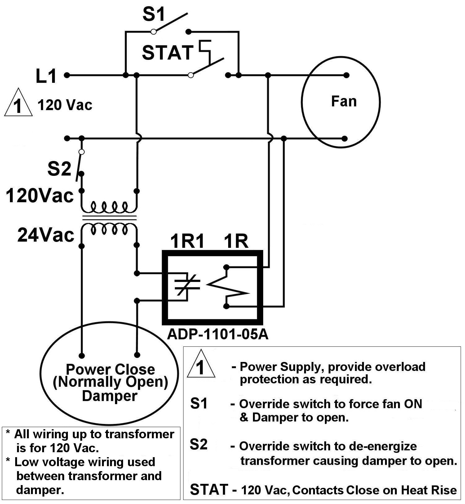
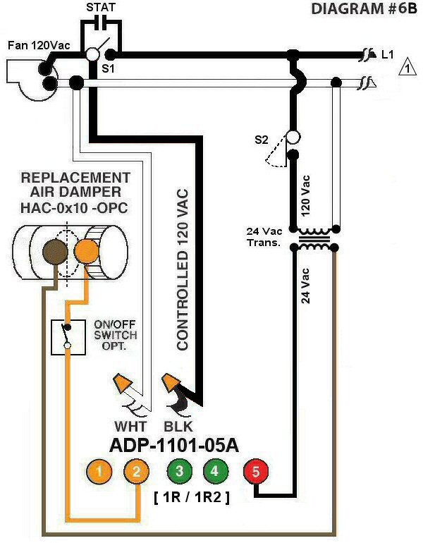
Diagram #6B: Economizer Circuit System to Ventilate a Computer Server Room using a cooling Thermostat, an Exhaust Fan, overriding switches, an Interface Relay Adaptor, a 24Vac Transformer and a Motorized 24Vac Power Close Damper.
- Thermostat, 120Vac contact on temperature rise
- Ventilation Fan
- Overriding Switches, 120Vac
- Interface Relay Adaptor (ADP-1101-05A)
- 24Vac Transformer
- Fail-safe-open 24Vac Motorized Air Control Damper, Power Close (HAC-0x10-OPO) where x= dia. of Damper)
OPERATION:
- Cooling Stat on temperature rise will turn on Ventilation Fan and open Fresh Air Inlet Damper
- Manual inline overriding switch will turn on Ventilation Fan and open Fresh Air Inlet Damper
- Secondary overriding switch to transformer will open Damper only
- Damper will Fail-Safe-Open in the event of power failure
Check our webpage, for Damper type ‘HCR’, for our Commercial Rooftop Economizer Damper.