
120Vac Vent Switch, Adaptor 1101 and Replacement Air Damper, Power Open:
#6A. 120vac Ventilation Fan Switch, Adaptor (ADP-1101-05A) and Power Open Replacement Air Damper (-PO) stays Closed during Furnace firing.
HMI Hoyme Manufacturing Inc. Special Note: Circuits are colored for clarification only and are not necessarily those found in actual installations. Combustion Air Damper Wires, however, are colored as shown.
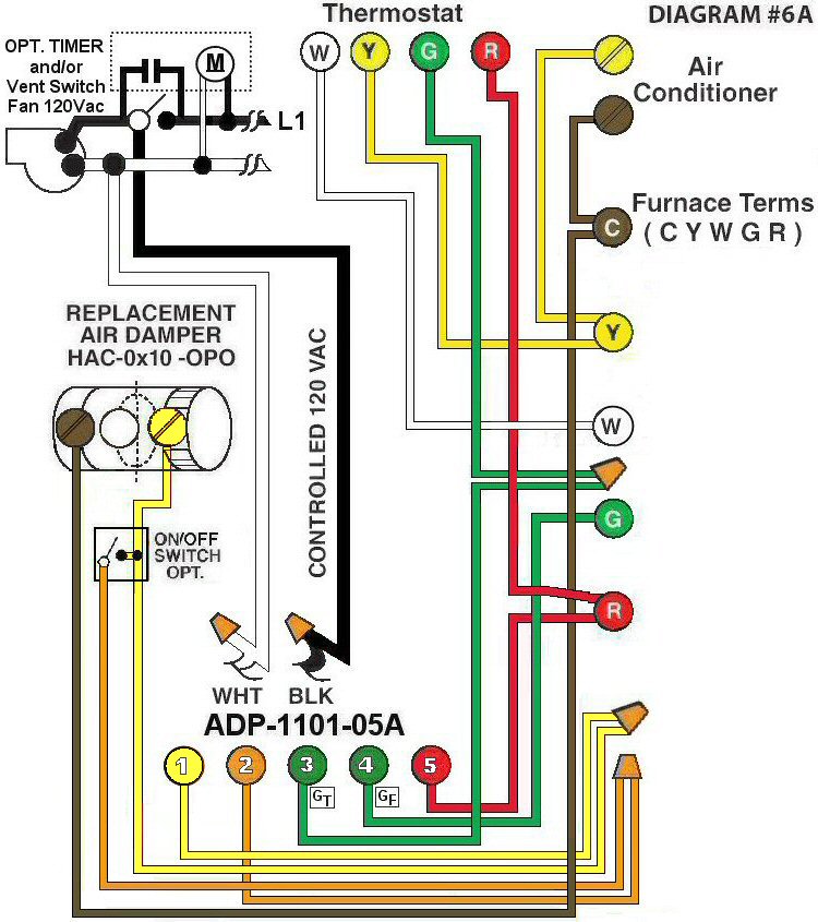
Diagram #6A: Forced Air Furnace having a Replacement Air Supply Duct together with an Exhaust Fan controlled by a designated Ventilation Switch and/or Bathroom Timer.
- Replacement Air Control Damper (PO) (HAC-0x10-OPO)
- Ventilation Switch and/or bathroom timer to supply Controlled 120Vac to Furnace area
- An optional ON/OFF Switch
- Relay Adaptor (ADP-1101-05A) to function as a control center
OPERATION:
- Furnace fires with Thermostat signal
- Ventilation Switch and/or bathroom timer turns on the Ventilation Fan, the Furnace Fan and opens the Ventilation Damper simultaneously with the Damper connected to Adaptor Terminal #1
- Optional Switch (i.e. toggle switch, timer, de-humidistat) connected between #1 and #2 of the Adaptor allows full control of the Replacement Air Damper to open as required
N.B. Replacement Air Damper is not affected by the ‘Manual’ setting of the Furnace Fan.