
Two Forced Air Furnaces sharing a Replacement Air supply Duct controlled by One Fresh Air Damper with Power Closed Damper:
#8C. Two Forced Air Furnaces Sharing a Replacement Air Duct with a Power Close Fresh Air Damper (HAC-0x11-OPC) c/w Relay Controlled by Adaptor (ADP-0241-05A).
HMI Hoyme Manufacturing Inc. Special Note: Circuits are colored for clarification only and are not necessarily those found in actual installations. Combustion Air Damper Wires, however, are colored as shown.
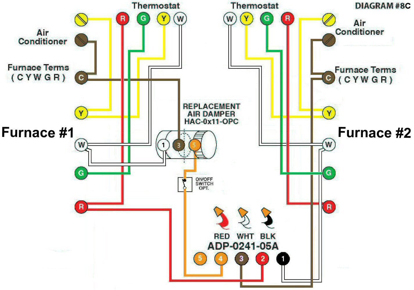
Diagram #8C: Two Forced Air Furnaces sharing a common Replacement Air Supply Duct controlled by one Power Close Fresh Air Damper with a Relay. The Damper opens when either Furnace fires.
- Replacement Air Control Damper with a relay, Power Close (HAC-0x11-OPC) where ‘x’ = diameter of the Damper
- 24Vac Relay Adaptor (ADP-0241-05A) to operate the Damper from either Furnace
OPERATION:
- Note: The Damper is a Power Close damper (PC) type so that if either Furnace fires the Damper will open and remain open until both Furnaces turn off
- Optional Switch will allow the Damper to open as required
N.B. Replacement Air Damper is not affected by the ‘Manual’ setting of the Furnace Fan or by the operation of an Air Conditioner.