
120Vac Vent Fans, Vent Switch, Timer Adaptor with 1102-TWP Adaptor, Replacement Air Damper (Power Close):
#9A5. Same as #9A4 but uses a Power Close Fresh Air Damper (HAC-0x10-OPC).
HMI Hoyme Manufacturing Inc. Special Note: Circuits are colored for clarification only and are not necessarily those found in actual installations. Combustion Air Damper Wires, however, are colored as shown.
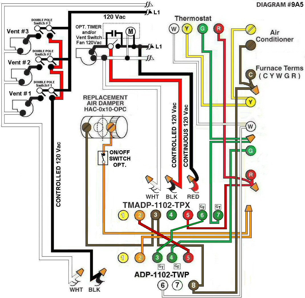
Diagram #9A5: Forced Air Furnace having a Replacement Air Supply Duct together with two (or more) Exhaust Fans controlled by two (or more) separate Double Pole Ventilation Switches, a Timer Adaptor and an Adaptor controlled by the Thermostat.
- Replacement Air Damper (HAC-0x10-OPC) to control Fresh Air Inlet
- Controlled 120Vac (3-Wires) from the main exhaust fan and controlled 120Vac (2-wire) from additional Exhaust Fans are required to the Furnace area
- Double Pole Ventilation Switches for two or more Exhaust Fans
- Relay Adaptor with Interval Timer (TMADP-1102-TPX) functions as the automatic control center together with Relay Adaptor (ADP-1102-TWP) allowing for additional Exhaust Fans to be added and also the Thermostat to be interconnected
OPERATION:
- Fresh air Damper opens during Furnace firing
- Ventilation Switch from any area and/or bathroom timer turns on Exhaust Fan opens Replacement Air Damper and turns on Furnace Fan simultaneously
- Adaptor Interval Timer can be set for minimum or multiple consecutive settings of 15 minutes to simultaneously turn on the principal Ventilation Fan open Replacement Air Damper and turn on the Furnace Fan
- Optional switch connected to the Damper and Terminals #2 of the (ADP-1102-TWP) Adaptor allows full control of the Power Close Replacement Air Damper to open as required
- Note: Power supply shall be from one Circuit
- When using a Power Open Damper, refer to Diagram #9A4
N.B. Replacement Air Damper is not affected by the ‘Manual’ setting of the Furnace Fan.